


SuperHoneyBadger
-
Posts
163 -
Joined
-
Last visited
-
Days Won
5
Content Type
Profiles
Forums
Downloads
Store
eMastercam Wiki
Blogs
Gallery
Events
Posts posted by SuperHoneyBadger
-
-
Thanks for taking a look, I appreciate the help! I'll update when the issue is resolved
-
Disclaimers: Heidenhain 3+2 Post, MC2024, Z2G posted, I don't have multi-axis.
Making a square based pyramid part, features removed in the Z2G.
Programming a toolpath on 1 face, then XForm it to the other 3 faces to match. Verify is good, machsim is good, backplot is good. I'm happy there.
Problem arises when I post them though, I get rotation calls but no datum calls (CYCLE DEF 247) when I transform exactly 1 toolpath with XForm. If I add 2 or more, each datum call is added before the rotations.
My planes are all setup nicely for how this machine runs, Datum1 = top/top/top, Datumx = top/planex/planex
I'm thinking I have to setup the XForm ops differently with a single toolpath vs multiple, but I'm not sure. I'll have to call IHS on Monday if I still can't figure it out. I need to make chips next week for sure.
-
Mill a bar on a flat boss
I love this thread
-
1 hour ago, cncappsjames said:
Thanks to <expletive> heads at Adobe, you can expect subscription ONLY model pricing for EVERY piece of software eventually.
What was it that Klaus Schwab said???? Oh yes; [quote]... you'll own nothing and like it...[/quote].

It sounds almost as if you don't want to pay for your family's food with Social Credit on a 48 month instalment plan administered by the UN Dept of Subscriptions? Odd stance to take.
-
 5
5
-
-
On 6/14/2021 at 9:20 AM, Corey Hampshire said:
Is there a way to set the default setup sheet and default machine to use in machine sim so that every time I load a specific machine those two things are set for me automatically? It seems there should be a way to tie them into a machine def setting or something along those lines. Those are two items that I have to set every part I do, and I feel like there should be a better way.
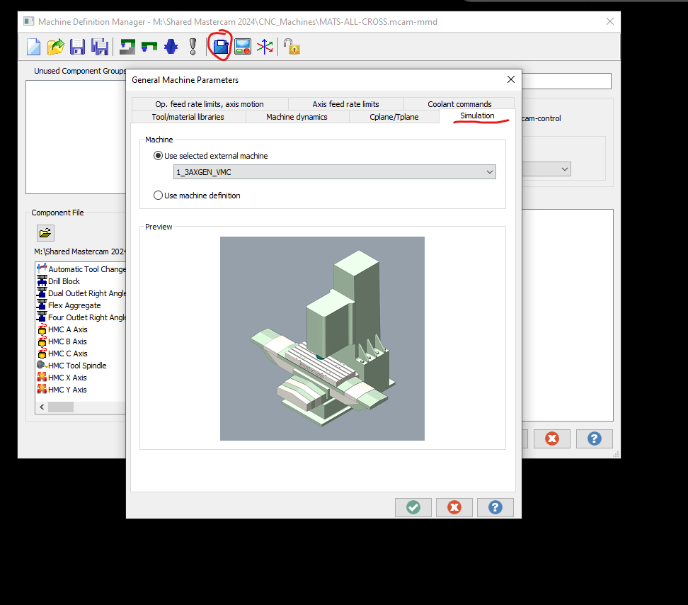
Been looking for a method to do this lately as well. Found it today!
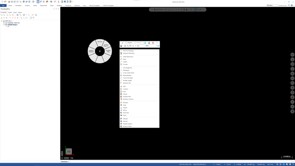
The menu to choose a Default Simulation Machine for a given Machine Def is under 'General Machine Parameters' in the Machine Definition Manager.
Found this thread last week while I was trying a few things out, wanted to update it with an answer. I'm using 2024 U6.

-
 1
1
-
 1
1
-
-
13 hours ago, Aaron Eberhard said:
All of those ribbon button-clicking skills are starting to bleed over into the rest of your life...
Same cat-like reflexes it takes to nab the big-red-button just in time.
I'll defer to decades of video games for those - mad tight ribbon skills are a happy consequence, lol
-
1
-
-
I can replicate by clicking a few links to the site quickly. Maybe 3 or 4 within a few seconds.

-
12 minutes ago, Aaron Eberhard said:
You have a solid that's been extruded from that 2"x1" rectangle. After manually manipulating the wireframe to extend it to 3"x1", the solid will be regenerated at the new size, so that is parametric.
I came up with SolidEdge and their "Synchronous" (insert trumpet fanfare) modelling. So the way I learned was the wireframe makes the initial solid, then, in MasterCam terms, you delete the wires and use the Push/Pull arrow, or Move to change a face/dimension. I never even thought to change the wireframe to resize a solid, as I immediately blow up the solid history. I have always really enjoyed making solids in MasterCam - as I progress, I do yearn for some associativity from time to time - but hey, this is CAM.
Also, from my understanding talking to a few SolidWorks guys "parametric" they use referring to some form of spreadsheet or table that can drive geometry with formulas and such? Am I off base with that?
-
3 hours ago, cruzila said:
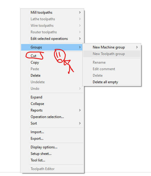
When you do that "cut" thing. STOP STOP STOP. You get one chance to then select "undo" from the same RMB. Click again, or do one other thing and it's lost
Holy molee, I have always reacted with a Ctrl+Z, and it never works. I'll try to stop next time and pull them from the fire.
4 hours ago, MWearne said:You can record a keystroke macro and trigger it from a keyboard shortcut or custom mouse button.
I have an mmo mouse I use for things like this. I think some non mmo still have the ability to do this as long as you have an extra button??
Had to update my 3Dconnexion software to get it to work, it was running the keys too fast and it happened before the flyout was available. The new update added delays to macros, so I pulled it off. Thanks again for the help. Actually ALL the help your resources have been over the years, appreciate it!
-
1
-
1
-
-
So, highlight the group, then it runs right click, arrow keys, enter.
I accept. Keysytroke macro on CadMouse, I never use the side nav buttons in MasterCam, so I'll set them up.
As an aside, I did notice that the cursor goes back to the toopath group you right clicked on automagically after clicking "New Toolpath group". So that does save some time too when manually adding. Thanks for the suggestion!
-
Thanks, appreciate the response, I figured it was going to be a no.
-
Pretty straightforward. Looking to assign "New Toolpath Group" to a keystroke.
This command only seems to exist inside the right-click menu of the Toolpaths Manager. Is it possible to assign it to a keystroke? I'll even accept some modifications or workarounds.
I do a lot of updating old programs (not through all 4000 yet), they usually have the OPs unorganized. I'll be lucky if G54 and G55 have separate groups, usually just divided by a comment.
So naturally I need to organize them when I open one up, and making multiple toolpath groups is a pain in the patoot. And at speed, I have often clicked "cut" on the way to the Groups flyout. There is no dialogue box or anything, your toolpaths are just poofed, and the red arrow now lives in the last group you made, so good luck pasting them back in the right spot. Anyways, kind of a long road, but that's the deal. A "New Toolpath group" shortcut would be useful.
-
22 minutes ago, crazy^millman said:
5 seconds of work answer both of your questions?
C'mon, Dad, we were just poking the new guy... Looked like the other spam this morning, I felt obliged to give him the gears.
I usually extrude>cut with dummy wireframes, this is better if the desired cut lies on a plane, thanks!
-
3
-
-
Danie Copperfield out here with the big CAD/CAM tricks.
Please teach me how to cut stuff in half, my guy. All my parts are whole still.
-
3
-
-
I used to get a similar error (can't be sure of the exact numbers) often, specifically when closing MC2023 on my machine. It never seemed to be an issue other than having to click to close the error, no data loss or problems. It did say MasterCam in the dialogue box title for me. If I can replicate, I'll add a screenshot.
Pursuant to the other responses, I no longer use Adobe Acrobat Reader, so maybe that was the issue. Not sure. I have not had the error since moving to MC2024 and Foxit Reader.
-
On 4/20/2024 at 12:47 AM, Tommy Thompson said:
We have a number of fanuc controlled vmcs from various machine tool mfgers. Most are oi-mf. The machines are generally great and the controls usually perform well but our shop is struggling to load the new high speed machining tool paths or multiple programs for part arrays onto the fanuc machines. Without engineering know how, adding memory or ftping or getting a control to recognize a cf card in an adapter to a pcmia port (must be the last place on earth for such a thing) is all extremely time consuming and frustrating. The tiny memory on the average fanuc control is hard to understand. I’d like to know why they do not just put a tb of memory on these machines or make them connect easily to a computer. It seems like it takes patient dedication or an cs degree to make them work. Endless nuance about partitioning cf cards, etc.,embedding ethernets. It might be fine for a large firm or some of the wizards out there, but for the average job shop, it’s a failure. If you are an engineer who speaks fanuc and wants to earn some money please let me know. If you want to say it’s a piece of cake, save it bro.
Our shop has a handful of 90s FANUC controls, lack of memory is my top concern when programming for those machines. I have a few thoughts that may help you out:
-You should look into an operation repeat macro to make multiple parts. It will save you from needing to use Xform + subs to make a bunch of parts. Our posts are set so that we can specify how many times we need to run a tool at the machine, based on setup needs, with a default of 1 part. At the end of the tool's work, it checks to see if there are any more offsets to run, then increments and re-runs, or moves to the next tool. Our machines use G54-9, J01-29, so we increment the J value to repeat multiple parts. YMMV based on your control and how many offsets you have available. This method lets you program for one, and make 3 at once. Then next time make 10 at once if you need to.
-Take a look at your filtering settings, and hi-speed ruff with 0.005-0.010 as the tolerance (~1/2 stock to leave usually). Be sure to check the box that says "Output 3D arc entry motion" too. That will clean up your helical entries. Know that while dynamic HSM is fun, and fast to program, if your machines can't handle it, they can't. Often a facing, pocket, contour or 2D blend toolpath with a 10% stepover can get you into HSM feed numbers and keep your tools running on lines and arcs.
These methods will take a bit more time and effort to set up, but well worth it for memory starved machines. I have run hi-speed, or hi-speed-lite™ on our machines with 60-128K of memory.
Also there is a lot of discussion on "why not drop 2TB SSDs into machine tools", and it boils down to the type of flash they used on these boards. They are designed to last for decades in a shop environment, and still work around the clock. There are threads here, and on PracticalMachinist if you want to look up the specifics. I'm not absolving the MTBs of the insane pricing for memory, but supply is scarce for old parts now too.
-
1
-
-
Your desired shape looks like a quadrant of a hemisphere, is that true? Might have some luck starting with a sphere and trimming it up with planar surfaces/wires to get what you're after. If not, nevermind me - I honestly thought it was a flat "shield" shape at first and was going to tell you to cut it out of a flat plane.
I've always had better luck trimming up surfaces to get what I want, as oppose to making the initial surface behave how I think it should come out.
-
https://cmailco.wordpress.com/2010/08/12/hey-who-stole-my-chip-load/
I wanted to share a quick read that really sparked my full understanding of RCTF, and the formula/theory involved. I never went to learnin' school for programming or machining, so maybe it's old news to those who have training, or have been in the game for a long time. But this really did the trick for me, and I have had the formula printed out and posted on my office wall for a few months. Helped me get out of the 0.0015" per tooth mindset that was hammered in around here.
My hope is that someone else who might be fuzzy on the concept, or new to it, might benefit from another/different explanation as I did.
-
4
-
-
Just had my 3Dx configs get messed up, so I'm getting them back in order, but I love the radial menu on the mouse. I know it's peripheral specific though, and not everyone is going to have a cadmouse.
RMB setup is key, probably 90% of my daily toolkit is on there.
Also, no matter what software, keyboard shortcuts have ALWAYS been my go to. I'm still adding to my list of MC keyboard combos, i think I added Dynamic Transform the other day: Shift+T. Always use Shift+F4 for Analyze Distance. Don't forget navigation shortcuts make you fast, and then you won't need a spacemouse.
Keyboard shortcuts are the Macro B of UI, fight me.
-
3
-
1
-
-
2 minutes ago, Newbeeee™ said:
Programmed by MasterCimaGibbs, post output using Postability, and simulated using IcamiCut verification.
One. Stop. Shop.
Sandvik's DynamiCAM© Suite 2026, monthy subs ready for pre-order now!
-
1
-
-
At least you guys had coolant and machine guards, lol! Impressed to see a knee mil running like that!
-
1
-
-
1 minute ago, Newbeeee™ said:
I have I nice vid of X4 dynamic pocketing a big ally block on a Prototrak 2axis SMX1500 mill running flat out at 4k rpm and 2000mm/min feedrate.
But this was 2009/2010 and I am soooo last Wednesday....
ProtoTrak DPM SX5 was the first NC machine I ever ran, ~2013, fond memories. Would be a messy job running HSM toolpaths on an open machine! We had to get out the cardboard box panel to deflect the facemill chips back then, lol.
-
1
-
1
-
-
1 minute ago, Aaron Eberhard said:
That's why you end up bidding against NASA on Ebay if you need 2 or 386 processors nowadays...
Oh man, I gotta check the grandparent's basement now.
Also makes me wish I had bought an IBM XT with a board instead of a bare chassis a few years ago, it's destined for a modern gaming rig so it only had the PSU inside. Never thought about reselling the innards at the time.
-
2
-
-
1 hour ago, JB7280 said:
I'm curious though, what is this "new stuff" that's way too slow and doesn't work in "real life"??
Maybe a servo-modded knee mill with a 4k spindle and DRO can't handle 2D dynamic ruffing? Dunno. Wouldn't be surprised if it was that kind of issue though... Buddy came in pretty hot, not really asking for assistance. I don't know if it comes from a place of technological ignorance, or wanting/needed something to work just as it has for a few years.
EVERYTHING wears out eventually, gotta have a plan in place for when the failures materialize!
-
1
-
4
-


How do you turn off the eyeball in the Tool Manager?
in Industrial Forum
Posted
Eyeball indicates that tool is the "Display Tool", right click a tool in the Tool Manager to set. Once you have a display tool set, it seems you can't unset it, but you can pick another one.