


Shiva.aero
-
Posts
95 -
Joined
-
Last visited
Content Type
Profiles
Forums
Downloads
Store
eMastercam Wiki
Blogs
Gallery
Events
Posts posted by Shiva.aero
-
-
1 hour ago, Colin Gilchrist said:
Your Post is not coupled to machine simulation, unless you specifically paid for it. You would know if you had it, because it would have been negotiated with the purchase of the Post.
We purchased as "5 axis bundle with post". So I am aware. Till reading this post, I was knowing about 'post linked to machine simulation' option. Also, I never heard such thing with my previous CAM.
Anyhow, I will reach out to my reseller to find it.
Thank you.
-
1 hour ago, JParis said:
AM I the only one that my ears perk up when someone is reseller averse?
Big red flag to me
My SMC is expired and I don't to disturb them, if there is a simple way to check. That's the reason I asked.
-
On 11/6/2021 at 2:21 AM, Colin Gilchrist said:
There are two different types of Machine Simulation:
- Generic, running the NCI Data only. No real knowledge of any "linking moves" or machine kinematics. Sure, you can build a simple "Machine Simulation" that will work for about 80-90% of regular Mastercam. But it won't be 100%.
- A "Machine Simulation Enabled Post Processor". This is where a Post Developer "adds code", to drive the Machine Simulation. This is "separate NC Output". It is not G-Code based. It is "Moduleworks Centerline Tool Data, and Machine Motion Commands". This couples the "Post output" with the "Machine Simulation Output". and gives you about 96% accuracy. If you add some crazy custom code to "make a machine approach move", you would also have to modify the MWCL output code, to "tell Simulation to show that same motion". But this does go far, far, beyond what a "non-Simulation" Post Processor can do.
You say you've "paid $2,500 for a Post already", but your current purchased Post Processor is not "Simulation-Ready". There is a massive amount of code which must not only be added to a regular Post, but you've also got to test both the "NC Code Output", and the "MWCL Simulation", and tweak each if necessary.
Starting with Mastercam 2022, if you want to run a "Simulation enabled Post Processor", you actually must purchase a Simulation License Module, because there is a revenue split between CNC Software and Moduleworks.
You can still get someone to build you a "generic simulation", but it isn't the same thing as a Reseller selling you a Post/Simulator (tied-together), and it is very much worth the money to have working software. It also means that anyone who wants to run a "Post/Simulation" combo, must purchase a license to do so. (This license is not required to run Generic Machine Simulation, as far as I know.)
Other than asking my reseller, Is there any way to check whether my Post is coupled to Machine simulator or not?
-
Any update to this post?
All these problems for NTX 2000 is just because of the Post Or is it due to the MC itself?
Is it all improved with MC2023?
-
Vericut supports VNCK.
I couldn't find any information regarding Ncsimul's VNCK support
Ncsimul has 'NCsimul 4CAM' module, which is an integrated post processor. This is one advantage of NCsimul compared to Vericut, but when I contacted Hexagon (India), they informed that the module is not fully functional.
If anybody has any information on NCsimul's VNCK support and NCsimul 4CAM module, then please share it here.
Thank you.
-
Hello all! Thanks for the suggestions.
1. I understand that it is a post problem. I gave all the inputs (output from MC, output from other CAM, etc.,) to my vendor (MC India) and they are working on it.
2. I asked my vendor for post which gives Vector outputs instead of angle outputs. This is just to check.
3. Contacted Siemens. They asked to ensure correct placement of Clamping & Unclamping codes.
I will update here once the problem is solved. Thank you.
-
 1
1
-
-
Hello all! During 5 axis machining, the machine stops with an error message of "Axis enable missing".
I observed that this happens when the execution changes from 3 axis line (block) to 5 axis line (block). For example, some of the line have only x, y and z value and when it reaches the line with x, y, z, B and C value, this error happens.
I also observed that changing the values/switching off of Cycle 832 (High speed machining cycle of sinumerik) have some effect on this error. That is, some time it continues to run with warning/alarm, or it sometimes stops at different block no.
Could it be the problem of post? Or any other settings in MC?
I don't get this problem when I run with program from different CAM. Just based on that I am ruling out machine / controller issue although I am not very sure.
Any help is appreciated.
Thank you.
-
Blade expert is super easy but it doesn't support Profiled tools like Oval/Barrel tools.
Now I want to create toolpath for the same blade using Morph toolpath, to use Oval tool, but the tool axis control is super complicated with lots of option.
1. Is there any good idea to set tool axis control for Morph toolpath by making use of generated Blade expert toolpath?
2. Morph toolpath has "Impeller normal to floor" option in Tool axis control. How does it differs from line control? It asks to select 3 blade edges. Any idea what are all those edges?
Thank you.
-
5 minutes ago, crazy^millman said:
Sorry I need an example file to share pictures. I can imagine hundreds of part in hundreds of machines so without a specific part, machine, and setup. If you're thinking about specific then anything I can imagine is not going to help. Mock something up then I can give my thoughts, but for me to just throw out something is going to create an echo chamber.
For example in Impeller part, during blade finishing with Morph toolpath, I like to control my B axis within -10 to 95 degree, since thats my machine limit. Just by trail & error, I could get the toolpath within limits by setting conical limits with respect to z axis. But I couldn't understand how it actually limits the B axis & if I want to use line option for this case, then where that line should be? I see the limits can be give only from 0 to 180 degrees but my machine can travel in negative B upto 10 degrees. How to specify this in limits?
Also whenever I limit the axis, I end up with a messy/wavy toolpath in some zones. I switch between exact & approximate step over calculation but still there will be some messy toolpath zone.
Right now I don't have example file. You may please consider the HTEC impeller from tech exchange.
Thank you!!!!
-
On 1/29/2022 at 7:36 PM, crazy^millman said:
What I normally do it draw a line normal to a feature I know on the machine will be the mid point of a rotation I want the machine to stay with in. I then use limits like and pick the last option conical limit. When a programmer picks that option they have X-Y-Z-Line-Dynamically to leading curve as options to use. I pick that line and will go from there. I might need to make it normal to the start of end of a rotation since it is limited to 0-180, but this works really great to limit certain conical limits on a machine. In 4th Axis Tool Axis control process then we don't really get a conical limit we get a angle limit. In full 5 axis under Tool Axis Control then we will lime our 2 Axis we have in the kinematics of our machine. IF you go look up CamInstructor I have a 5 Axis part I shared with them and it as lot of different toolpaths and process crammed into it. We didn't go over limits, but any programmer can use ti to get a grasp of different thing they can do with 5 Axis toolpaths.
Can you please share some pictures on this? & Can you please elaborate on this
"I might need to make it normal to the start of end of a rotation since it is limited to 0-180"
-
How to display toolpath which traces Tool contact point instead of Tool tip?
When I use Lolipop or ball end mill, I am not really sure whether the tool runs on the boundary edges or not and some linking motions are really confusing. When I backplot it, I understand those moves happens to keep the tool in contact. If we can change the toolpath display from Tooltip to Tool contact point, then I hope it will be easy to understand especially when we use Lolipop end mills.
Thank you!
-
On 1/3/2022 at 11:30 PM, Colin Gilchrist said:
Check out this thread for some information on modifying your Chip Load "on-the-fly", by looking at the Arc Radius of the Tool, Path, and the "Linear Feed at Tool Center", versus "Linear Feed value at the Tool Periphery".
What if there are no G2 & G3 in the code? I mean approximating every Arc moves into linear moves. Will the overfeeding still occurs?
-
22 minutes ago, cncappsjames said:
Negative. New patent issued in 2014.
https://www.tenlinks.com/news/celeritive-technologies-gets-2nd-us-patent-for-volumill/
This old post explains it better
Is it possible that MC adjusts engagement angle instead of keeping it constant, to compensate for the increase in chip load due to Arc moves, instead of varying the feedrate?
-
19 hours ago, mwearne said:
Constant chip load, no it doesn't. Constant engagement angle, yes.
I'm not exactly sure why there is not an option to keep a constant chipload or maybe even MRR constant, I assume it is a patent infringement on someone elses toolpath as it seems like a no brainer to have this option in Dynamic. As is, we are over feeding on internal features and under feeding on external.
...I think there is mention in a posting somewhere here of handling this in the post processor. No idea how well it works as I've not tested it.
Of course, not all will agree with me so I leave you this...
.gif ":)")

Plz check this link. It says "constant chip load"
https://www.mmsonline.com/articles/boost-metal-rates-with-constant-chip-load-machining
-
18 hours ago, mwearne said:
Constant chip load, no it doesn't. Constant engagement angle, yes.
I'm not exactly sure why there is not an option to keep a constant chipload or maybe even MRR constant, I assume it is a patent infringement on someone elses toolpath as it seems like a no brainer to have this option in Dynamic. As is, we are over feeding on internal features and under feeding on external.
...I think there is mention in a posting somewhere here of handling this in the post processor. No idea how well it works as I've not tested it.
Of course, not all will agree with me so I leave you this...
So the Dynamic toolpath maintains constant engagement angle in the corner, but it increases the chipload! What ultimate advantage we are getting from it?
As show in the excel, we need to have very high toolpath radius to avoid overfeeding the tool and when I give more toolpath radius for pocket milling, it almost look like a helical milling.
-
8 hours ago, cncappsjames said:
Waspalloy is VERY unforgiving material. . Plunging even 25μm and your tool is as good as cooked. You have to ramp in Z any transition from one depth to another.
On another note, it is VERY possible that an inside corner transition created by arc filtering caused a sudden increase in chip thickness thus blowing up your tool. Of all the materials I've cut, Waspalloy is in the top 3 or 4 most difficult to cut. By difficult I mean that I have to think about every motion in the path and it's potential effect on the tool.
HTH
Thank you! It's a pocket machining. So I drilled a 5.5mm hole and the entry to next level is by plunging inside this hole (I put zero for vertical Arc entry & used only horizontal Arc entry).
What do you mean by Corner transition?
I doubt increase in chip load when the toolpath radius goes small & that's why created another topic:
-
On 12/30/2021 at 7:30 PM, crazy^millman said:
Without seeing the program and exact parameters no way to really know.
#1 I never use smoothing on any program so I cannot comment on what it could or could not do to the program.
#2 Very possible is you were not using accel and deaccel on the machine.
#3 None i can think of and repeat what I opened with. Many times we don't see the linking moves before doing something like this and with the linking parameter not set correctly they were not creating the issue before you filtered the toolpath, but after the just little difference in line segments to arcs is enough to overload the tool in or out of an area. Try increasing them and see if that is the culprit here.
Did it break in the same exact spot or somewhere different? What is the material? Speed and feeds? Other cutting parameters? Taper of the machine? Type of holder?
Material is Wasploy. Dia 5mm tool with corner radius 0.3mm. Speed is 30 m/s and Feed per tooth is 0.025mm and I switched on the RCTF since I use dynamic toolpath (& it modifies the speed & feed). Depth of cut is 1.5 mm and engagement angle is 32.5 degree. Tool make is Walter. Tool overhang is 50mm. HSK taper and tool holder type is Shrink fit holder with length 80mm. Am I working on the verge of breaking the tool or is there enough margin?
Thank you!
-
There is an excellent video on the topic of Avoid breaking cutters by Caminstructor youtube channel and here is the link
Here in this videos, the author discussed about how the Feed per tooth increases, when tool follows the curvilinear/curved tool path. After watching this video, I got the following doubt:
1. What should be "minimum toolpath radius" for 'Optirough toolpath' for the given cutter size to avoid overloading?
2. Dynamic toolpath is used for constant chip load by keeping engagement angle constant . If the chip load can be increased due to the difference in 'tool contact point feed rate' and 'tool center point/toolpath feed rate', then are we not loosing the advantage of maintaining the 'constant engagement angle' by 'increasing the tool contact point feed rate', because of the curvilinear/curved tool path generated by Dynamic toolpath?
Regarding the #1, I decided to derive the formula from the basics to understand it better and also by taking the same example shown in the video.
That is machining a 0.55" (13.97mm) hole with 0.5"(12.7 mm) cutter with the toolpath radius of 0.05"(1.27mm) with 30 inches/minute feed rate (760 mm/min).
Now, even though the 'tool-contact / peripheral feed rate' different is 'toolpath' feed rate, the angular speed of both should be same. So,
Angular speed of tool-contact point = Angular speed of toolpath
since, Angular speed = Linear speed / radius of curvature. (Linear speed is the feed rate)
"feedrate-toolcontact-point" / (toolpath radius + tool radius) = "feedrate of toolpath" / toolpath radius
now, feedrate at toolcontact-point = ( (toolpath radius + tool radius) / toolpath radius) * feedrate of toolpath
= ((0.05"+0.5") / 0.05)* 30 inch/min (used dia. since it is a ratio)
= 11 * 30 inch/min = 330 inch/min! (11 times more chip load!)
Now modified feedrate of toolpath = ( toolpath radius / (toolpath radius + tool radius) ) * required feed rate at the toolcontact point
= 0.09 * 30 inch/min = 2.7 inch/min
Now the thing is that, even if we increase minimum toolpath radius equal to that of the cutter radius or even twice of it, there is a significant increase in the toolcontact point feed rate!. I attached an excel sheet to play with. This will make very difficult to machine the corners for difficult-to-cut materials even with dynamic toolpath. So after checking this, i got the question #2!
Please let me know if there is any mistake in the understanding or calculation.
-
1
-
-
22 hours ago, Chally72 said:
It's not just acceleration, but stuttering/lag- especially if you were on the limits of what the tool can do. Your specific machine behavior with G2/G3 and G1, and transitioning between them, should guide if you use these settings- not just the reduced line count factor. Some machines will stutter badly when transitioning through arc moves, and this can really hammer the tool with all the stop/go changes rather than staying properly in the cut.
The next question- what was your goal with the filtering to begin with? Was it just to reduce program size? Why- to avoid drip feeding? If the program fit on the control, adding in filtering is basically trying to fix a problem that doesn't exist.
Was the machine already stuttering with the current code before you added filtering, and this is what you were trying to address?
Knowing your goals with these options, and knowing what your machine likes to see (linearized code or arcs, more point density or less) is critical to seeing beneficial results when making changes in these options.
Thank you!
#1 I don not understand what is stuttering & how to check it in the machine. I use Cycle832 which is the High speed settings for the siemens840d controller.
#2 I used filtering just to reduce the no. of codes, because with the 100s of transform operation, the length of program was too long (even after splitting the transform operations) & it was difficult to perform GOTO or skip operations.
-
23 hours ago, crazy^millman said:
Without seeing the program and exact parameters no way to really know.
#1 I never use smoothing on any program so I cannot comment on what it could or could not do to the program.
#2 Very possible is you were not using accel and deaccel on the machine.
#3 None i can think of and repeat what I opened with. Many times we don't see the linking moves before doing something like this and with the linking parameter not set correctly they were not creating the issue before you filtered the toolpath, but after the just little difference in line segments to arcs is enough to overload the tool in or out of an area. Try increasing them and see if that is the culprit here.
Did it break in the same exact spot or somewhere different? What is the material? Speed and feeds? Other cutting parameters? Taper of the machine? Type of holder?
Thank you!
# none of the linking parameter & toolpath changed before and after filtering.
# No it did not break at the same spot!. All the things like material, speed, feed, etc., remained same.
-
Hello all!
I introduced Line/Arc filtering for the program which we were cutting regularly, after watching this video:
I just activated Line/Arc filtering & smoothing (5%) without altering any other parameter. Impressively it reduced the no. of code line from 215000 to mere 85000. However when I ran on the machine, the cutter broke! Once again I tried with another cutter & once again it broke!
I understand many other parameter like tool runout, coolant, etc., could have caused it, but I like to understand the influence of line/Arc filtering on the tool wear & tool load.
1. It's a roughing program and I activated smoothing option (just 5%). Could it be the problem?
2. Is it possible that, with the G2 & G3 the machine tool could accelerate really faster compared with the normal G1 codes, which caused increased chip load?
3. Is there anything else I should take care while using line/Arc filtering?
Thank you!
-
21 hours ago, Chally72 said:
Hey Shiva,
There are a few levers we can pull in multiaxis paths to enact surface finish changes without just adding zeroes to the cut tolerance. Take a look at controls like Damp on the Cut pattern page, and especially all the controls like Points Distribution and Smoothing on the Cut Pattern Subpage, "Advanced Options for Surface Quality". That's where you'll find most of the like for like options.
In short, ignoring the arc settings which aren't applicable to linearized multiaxis code, most of the controls you see on the 3 axis paths do exist in one form or another across different areas of (most of) the multiaxis toolpaths, just not organized the same. You've also got tool posture to think about at all stages of the calculation, which is the single biggest contributor to scrubbing, slowdown, micro-gouging/stippling/etc that can affect the end result.
Check out this video which walks through methods of improving a multiaxis toolpath for surface finish. Hopefully it gives you some ideas on thinking about how to tweak your specific application for the best motion:
Thank you!!!
-
Is there any equivalent to '3D Line/Arc filtering & smoothing' option for Multiaxis toolpaths, to get good surface finish without tightening the cut tolerance?
-
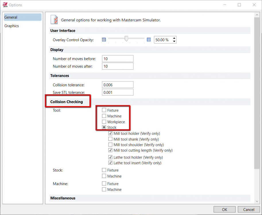
Can anybody please explain the Collsion checking options in MC simulator (Verify-> File ->Options)?
1. Why there are 3 categories (tool, stock & machine) ?
2. The options Fixture & Machine are with all 3 categories. How they are different?
3. Some of the options under tool category are indicated as "verify only". What does it means?
4. What should be relative value of Collsion tolerance in relation to the cut tolerance?
Please check the attachment for the image of verify option page.
Machine Simulation
in Post Processor Development Forum
Posted
My company owns both Esprit CAM and Mastercam. We are in the process of procuring NTX 2000. My management has given me option to purchase 'Millturn module & post' for either Esprit CAM Or Mastercam.
I am a Esprit Cam user for last 4 years and Mastercam user for last 1 year. Still I prefer Mastercam over Esprit. But after going through this thread, I really worry that my choice might be wrong.
If post is the only problem, then I can go for Postability Or In-house solution Post. Any suggestion will be much helpful.
Thank you.