Shiva.aero
-
Posts
95 -
Joined
-
Last visited
Content Type
Profiles
Forums
Downloads
Store
eMastercam Wiki
Blogs
Gallery
Events
Everything posted by Shiva.aero
-
My company owns both Esprit CAM and Mastercam. We are in the process of procuring NTX 2000. My management has given me option to purchase 'Millturn module & post' for either Esprit CAM Or Mastercam. I am a Esprit Cam user for last 4 years and Mastercam user for last 1 year. Still I prefer Mastercam over Esprit. But after going through this thread, I really worry that my choice might be wrong. If post is the only problem, then I can go for Postability Or In-house solution Post. Any suggestion will be much helpful. Thank you.
-
We purchased as "5 axis bundle with post". So I am aware. Till reading this post, I was knowing about 'post linked to machine simulation' option. Also, I never heard such thing with my previous CAM. Anyhow, I will reach out to my reseller to find it. Thank you.
-
My SMC is expired and I don't to disturb them, if there is a simple way to check. That's the reason I asked.
-
Other than asking my reseller, Is there any way to check whether my Post is coupled to Machine simulator or not?
-
Any update to this post? All these problems for NTX 2000 is just because of the Post Or is it due to the MC itself? Is it all improved with MC2023?
-
Vericut supports VNCK. I couldn't find any information regarding Ncsimul's VNCK support Ncsimul has 'NCsimul 4CAM' module, which is an integrated post processor. This is one advantage of NCsimul compared to Vericut, but when I contacted Hexagon (India), they informed that the module is not fully functional. If anybody has any information on NCsimul's VNCK support and NCsimul 4CAM module, then please share it here. Thank you.
-
Hello all! Thanks for the suggestions. 1. I understand that it is a post problem. I gave all the inputs (output from MC, output from other CAM, etc.,) to my vendor (MC India) and they are working on it. 2. I asked my vendor for post which gives Vector outputs instead of angle outputs. This is just to check. 3. Contacted Siemens. They asked to ensure correct placement of Clamping & Unclamping codes. I will update here once the problem is solved. Thank you.
-
Hello all! During 5 axis machining, the machine stops with an error message of "Axis enable missing". I observed that this happens when the execution changes from 3 axis line (block) to 5 axis line (block). For example, some of the line have only x, y and z value and when it reaches the line with x, y, z, B and C value, this error happens. I also observed that changing the values/switching off of Cycle 832 (High speed machining cycle of sinumerik) have some effect on this error. That is, some time it continues to run with warning/alarm, or it sometimes stops at different block no. Could it be the problem of post? Or any other settings in MC? I don't get this problem when I run with program from different CAM. Just based on that I am ruling out machine / controller issue although I am not very sure. Any help is appreciated. Thank you.
-
Blade expert is super easy but it doesn't support Profiled tools like Oval/Barrel tools. Now I want to create toolpath for the same blade using Morph toolpath, to use Oval tool, but the tool axis control is super complicated with lots of option. 1. Is there any good idea to set tool axis control for Morph toolpath by making use of generated Blade expert toolpath? 2. Morph toolpath has "Impeller normal to floor" option in Tool axis control. How does it differs from line control? It asks to select 3 blade edges. Any idea what are all those edges? Thank you.
-
For example in Impeller part, during blade finishing with Morph toolpath, I like to control my B axis within -10 to 95 degree, since thats my machine limit. Just by trail & error, I could get the toolpath within limits by setting conical limits with respect to z axis. But I couldn't understand how it actually limits the B axis & if I want to use line option for this case, then where that line should be? I see the limits can be give only from 0 to 180 degrees but my machine can travel in negative B upto 10 degrees. How to specify this in limits? Also whenever I limit the axis, I end up with a messy/wavy toolpath in some zones. I switch between exact & approximate step over calculation but still there will be some messy toolpath zone. Right now I don't have example file. You may please consider the HTEC impeller from tech exchange. Thank you!!!!
-
Can you please share some pictures on this? & Can you please elaborate on this "I might need to make it normal to the start of end of a rotation since it is limited to 0-180"
-
How to display toolpath which traces Tool contact point instead of Tool tip? When I use Lolipop or ball end mill, I am not really sure whether the tool runs on the boundary edges or not and some linking motions are really confusing. When I backplot it, I understand those moves happens to keep the tool in contact. If we can change the toolpath display from Tooltip to Tool contact point, then I hope it will be easy to understand especially when we use Lolipop end mills. Thank you!
-
Avoid Breaking cutters by Caminstructor
Shiva.aero replied to Shiva.aero's topic in Industrial Forum
What if there are no G2 & G3 in the code? I mean approximating every Arc moves into linear moves. Will the overfeeding still occurs? -
Avoid Breaking cutters by Caminstructor
Shiva.aero replied to Shiva.aero's topic in Industrial Forum
This old post explains it better Is it possible that MC adjusts engagement angle instead of keeping it constant, to compensate for the increase in chip load due to Arc moves, instead of varying the feedrate? -
Avoid Breaking cutters by Caminstructor
Shiva.aero replied to Shiva.aero's topic in Industrial Forum
Plz check this link. It says "constant chip load" https://www.mmsonline.com/articles/boost-metal-rates-with-constant-chip-load-machining -
Avoid Breaking cutters by Caminstructor
Shiva.aero replied to Shiva.aero's topic in Industrial Forum
So the Dynamic toolpath maintains constant engagement angle in the corner, but it increases the chipload! What ultimate advantage we are getting from it? As show in the excel, we need to have very high toolpath radius to avoid overfeeding the tool and when I give more toolpath radius for pocket milling, it almost look like a helical milling. -
Broke the cutter with Line/Arc filtering
Shiva.aero replied to Shiva.aero's topic in Industrial Forum
Thank you! It's a pocket machining. So I drilled a 5.5mm hole and the entry to next level is by plunging inside this hole (I put zero for vertical Arc entry & used only horizontal Arc entry). What do you mean by Corner transition? I doubt increase in chip load when the toolpath radius goes small & that's why created another topic: -
Broke the cutter with Line/Arc filtering
Shiva.aero replied to Shiva.aero's topic in Industrial Forum
Material is Wasploy. Dia 5mm tool with corner radius 0.3mm. Speed is 30 m/s and Feed per tooth is 0.025mm and I switched on the RCTF since I use dynamic toolpath (& it modifies the speed & feed). Depth of cut is 1.5 mm and engagement angle is 32.5 degree. Tool make is Walter. Tool overhang is 50mm. HSK taper and tool holder type is Shrink fit holder with length 80mm. Am I working on the verge of breaking the tool or is there enough margin? Thank you! -
There is an excellent video on the topic of Avoid breaking cutters by Caminstructor youtube channel and here is the link Here in this videos, the author discussed about how the Feed per tooth increases, when tool follows the curvilinear/curved tool path. After watching this video, I got the following doubt: 1. What should be "minimum toolpath radius" for 'Optirough toolpath' for the given cutter size to avoid overloading? 2. Dynamic toolpath is used for constant chip load by keeping engagement angle constant . If the chip load can be increased due to the difference in 'tool contact point feed rate' and 'tool center point/toolpath feed rate', then are we not loosing the advantage of maintaining the 'constant engagement angle' by 'increasing the tool contact point feed rate', because of the curvilinear/curved tool path generated by Dynamic toolpath? Regarding the #1, I decided to derive the formula from the basics to understand it better and also by taking the same example shown in the video. That is machining a 0.55" (13.97mm) hole with 0.5"(12.7 mm) cutter with the toolpath radius of 0.05"(1.27mm) with 30 inches/minute feed rate (760 mm/min). Now, even though the 'tool-contact / peripheral feed rate' different is 'toolpath' feed rate, the angular speed of both should be same. So, Angular speed of tool-contact point = Angular speed of toolpath since, Angular speed = Linear speed / radius of curvature. (Linear speed is the feed rate) "feedrate-toolcontact-point" / (toolpath radius + tool radius) = "feedrate of toolpath" / toolpath radius now, feedrate at toolcontact-point = ( (toolpath radius + tool radius) / toolpath radius) * feedrate of toolpath = ((0.05"+0.5") / 0.05)* 30 inch/min (used dia. since it is a ratio) = 11 * 30 inch/min = 330 inch/min! (11 times more chip load!) Now modified feedrate of toolpath = ( toolpath radius / (toolpath radius + tool radius) ) * required feed rate at the toolcontact point = 0.09 * 30 inch/min = 2.7 inch/min Now the thing is that, even if we increase minimum toolpath radius equal to that of the cutter radius or even twice of it, there is a significant increase in the toolcontact point feed rate!. I attached an excel sheet to play with. This will make very difficult to machine the corners for difficult-to-cut materials even with dynamic toolpath. So after checking this, i got the question #2! Please let me know if there is any mistake in the understanding or calculation. Equivalent feedrates.xlsx
-
Broke the cutter with Line/Arc filtering
Shiva.aero replied to Shiva.aero's topic in Industrial Forum
Thank you! #1 I don not understand what is stuttering & how to check it in the machine. I use Cycle832 which is the High speed settings for the siemens840d controller. #2 I used filtering just to reduce the no. of codes, because with the 100s of transform operation, the length of program was too long (even after splitting the transform operations) & it was difficult to perform GOTO or skip operations. -
Broke the cutter with Line/Arc filtering
Shiva.aero replied to Shiva.aero's topic in Industrial Forum
Thank you! # none of the linking parameter & toolpath changed before and after filtering. # No it did not break at the same spot!. All the things like material, speed, feed, etc., remained same. -
Hello all! I introduced Line/Arc filtering for the program which we were cutting regularly, after watching this video: I just activated Line/Arc filtering & smoothing (5%) without altering any other parameter. Impressively it reduced the no. of code line from 215000 to mere 85000. However when I ran on the machine, the cutter broke! Once again I tried with another cutter & once again it broke! I understand many other parameter like tool runout, coolant, etc., could have caused it, but I like to understand the influence of line/Arc filtering on the tool wear & tool load. 1. It's a roughing program and I activated smoothing option (just 5%). Could it be the problem? 2. Is it possible that, with the G2 & G3 the machine tool could accelerate really faster compared with the normal G1 codes, which caused increased chip load? 3. Is there anything else I should take care while using line/Arc filtering? Thank you!
-
Thank you!!!
-
Is there any equivalent to '3D Line/Arc filtering & smoothing' option for Multiaxis toolpaths, to get good surface finish without tightening the cut tolerance?
-
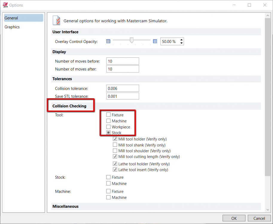
Can anybody please explain the Collsion checking options in MC simulator (Verify-> File ->Options)? 1. Why there are 3 categories (tool, stock & machine) ? 2. The options Fixture & Machine are with all 3 categories. How they are different? 3. Some of the options under tool category are indicated as "verify only". What does it means? 4. What should be relative value of Collsion tolerance in relation to the cut tolerance? Please check the attachment for the image of verify option page.