


aaron tabor
-
Posts
57 -
Joined
-
Last visited
Content Type
Profiles
Forums
Downloads
Store
eMastercam Wiki
Blogs
Gallery
Events
Posts posted by aaron tabor
-
-
I was testing something with a right and left turning tool, I generated the program and it seems to be missing a g41,g42 tool compensation code. I used the default processor and a haas st lathe processor and both gave the same result. Is this something you will have to go in and add manually?
-
2 hours ago, JParis said:
Do you have stock defined?
That's one many people miss
I had it set to use stock as outer boundary but then set it to remaining stock as rekd suggested which didn't work so I don't get it usually doing boring toolpaths goes through without an issue.
-
1 hour ago, #Rekd™ said:
Set the stock to remaining stock and re-chain your geometry.
I tried doing remaining stock and I rechained it with the arrow facing outwards along the inside contour but its still giving me the embedded in stock error.
-
I am working on a mastercam lathe tutorial I am trying to rough out a bore with a boring bar, I chain my geometry pick the right size tool, have the right lead in/out set but the tool wants to bury into the part past where its supposed to cut. It will either give me an error or generate the toolpath with the tool way too deep. I included a link to the file so you can see what I am saying (toolpath #8).
https://www.dropbox.com/s/ykrxkjav5azvo7q/Tutorial%205%20review%20with%20toolpaths.emcam?dl=0
-
I am doing a lathe tutorial and one of the toolpaths I programmed appears to be cutting correct in backplot following the parts boundaries, but when I run the part in verify instead of following the outside boundary it cuts across a curve. The toolpath I'm referring to is #11 finish operation I included a link to download the file so you can see what I am saying.
https://www.dropbox.com/s/x6qwrmk1s4imfn2/Tutorial%206%20review%20with%20toolpaths%20%233.emcam?dl=000
-
I am doing a lathe tutorial and I am having a problem with 2 toolpaths. Toolpath #10 is roughing the part and instead of cutting to the edge of the stocks boundary its cutting into the part where it shouldn't, I changed the leadout to what seems like the right angle but its still cutting into the part. I am also having an issue with the finish toolpath that follows it says that the tool is starting embedded in the stock so I increased the length of the line past the end of the stock, it didn't fix it I also extended the lead in but that also isn't working. I included a download link for the part I am referring to.
https://www.dropbox.com/s/eida0kxl19slhnx/Tutorial%206%20review%20with%20toolpaths%20%232.emcam?dl=0
-
Ok thats what I was doing wrong thanks for the help.
2 minutes ago, crazy^millman said:Shortening it? The holder is at at angle it would need to be extended a good deal.
-
Yeah I tried changing the c setting on the holder shortening it and it still is colliding with the part.
16 minutes ago, crazy^millman said:You have to change the holder not the insert.
-
It is an educational file so thats probably why but maybe a future update for mastercam should be lathe tool projection because editing different parameters for example increasing the C setting on the tool and decreasing it on the holder isn't working I know I could draw the tool and the holder but I just think it should be easier than that.
6 minutes ago, Jespertech said:unfortunately I can't open the file you shared it's either a mcam 2023 or a home learning edition file. I'm still currently sticking to 2022 at work.
-
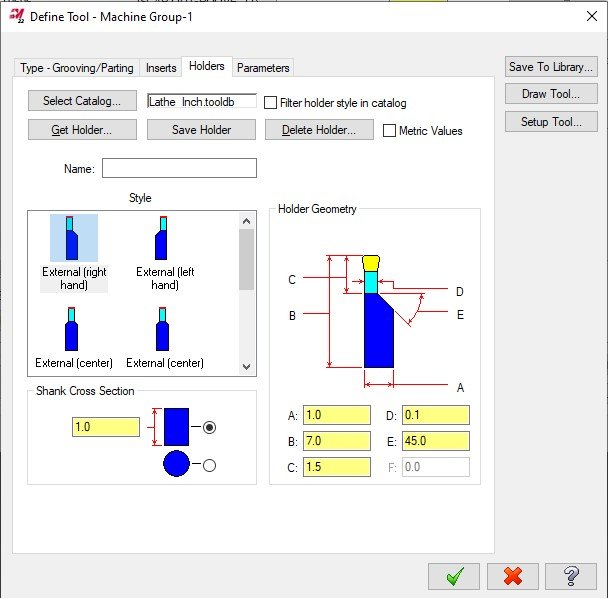
I did that but it doesnt change the length of the end of the tool holder and when I change the length of tool instead of sticking out more it just goes farther up inside the tool holder I'll show you the part I am referring to maybe you can figure it out also the toolpath I am referring to is #7.
https://www.dropbox.com/s/ria1au0j20qoajv/EXERCISE%20%233%20with%20toolpaths.emcam?dl=0
10 minutes ago, Jespertech said:right click tool in library, edit tool , then adjust the dimensions highlighted in yellow.
-
Is it possible to edit the tool projection on a lathe tool? I am programming a part and the tool holder is taking off a corner of the part because the tool is not sticking out far enough when doing a groove operation.
-
I tried that and it is still cutting into the part instead of following the chain I selected.
1 hour ago, AHarrison1 said:From what i can see, according to your geometry selection, the toolpath is behaving as it should within the constraints of what you have selected.
Re-select the chain starting from the origin.
-
I am doing a lathe tutorial and I'm having a problem programming a groove toolpath. I select the geometry correct but for some reason its cutting inside the part instead of following the outer boundary. I included a link to a file of the part so you can see what I am talking about.
https://www.dropbox.com/s/fno76s8dftemk8f/TUTORIAL%20%233%20groove%20operation.emcam?dl=0
-
3 hours ago, #Rekd™ said:
Your 2d geometry is in the wrong plane. Rotate it 90 degrees so it is visible in the top view.
Did you notice that the toolpath doesn't follow the geometry of the helix that I created? Its off to one side even though I "unrolled" the helix and created the line for the contour properly. I turned compensation off too so the line would be on center with the tool so its not that.
-
I am doing a 4-axis tutorial, I am trying to program a contour toolpath for a cylindrical helix I entered in all the information correctly as far as I can tell so I don't understand why its not generating the toolpath correctly. I included a link to the file so you can see what I am talking about also I'm refering to toolpath 3.
https://www.dropbox.com/s/fwneckjonna9vdg/4X-Lesson-4-ExA%20with%20toolpaths.emcam?dl=0
-
I am doing a 4-axis caminstructor tutorial, I am trying to program a cylindrical helix (pi*diameter*# of revolutions) but when I generate the toolpath instead of cutting on exactly where its supposed to its off a bit. I included a link to the download (file is too big) so you can see what I am saying.
https://www.dropbox.com/s/3fs6vff0m7xdgxo/4X-Lesson-4%20with%20toolpaths.emcam?dl=0
-
8 minutes ago, JParis said:
Look at the X axis direction of all your planes....assuming a rotary on the right. The X+ should be pointing right...I'll bet you have one pointing left
As always, the best way to get help is share a file
You were completely right I had to change the direction of the arrow of the x-axis and now it generated the program correctly. I appreciate your help.
-
 1
1
-
-
On 3/2/2004 at 9:22 AM, Roger Martin from CNC Software said:
It's been covered several times, here is the thread with the best explanation ->
That thread is no longer available and I am getting this issue is there someone I can talk to?
-
Yeah that works it just leaves some of the material behind at the outside corners its not a big deal though I could just do a contour toolpath along the edge clean it quick. . I think its just the part has an issue somewhere making automatic region on that section of the part impossible because automatic region worked on the flats next to the diameter.
-
I am having a problem with a 4 axis tutorial to I am trying to area mill a part, I select the machining region I use the automatic region selection, I set my paramaters correct as far as I can tell. But when I generate the toolpath it says "all machining regions have no material remaining" I dont understand why its doing this and I am hoping someone can help me. I included a link to the file so you can see what I am saying. (file is too big to upload)
https://www.dropbox.com/s/9xgfrs0dcy4e4xa/4X-Lesson-3-ExA%20with%20toolpaths.emcam?dl=0
-
2 minutes ago, #Rekd™ said:
Change the Rotary Axis settings as per the photo. There is no geometry to unroll or roll.

That worked thanks
-
I'm doing a caminstructor 4-axis tutorial I get to a point where I am supposed to drill a hole at an angle, I use axis substitution and set everything right as far as I can tell but instead of drilling straight into the hole its coming from the right at like 45 degrees I added a link so you can see the file.(file was too big to upload so i used dropbox)
https://www.dropbox.com/s/i2yvacw3rejipne/4%20axis%20tutorial%201%20with%20toolpaths%20solid.emcam?dl=0
-
I added a tooling a ball to this fixture from a mastercam tutorial. I did Solid mesh and then selected the origin as the center of the ball you will see what I am saying if you click the link and download the file, (file was too big too upload) this is how its done correct? https://www.dropbox.com/s/aj219rp5tif64bt/TUTORIAL%207%20UNIFIED%20PART2%20with%20tooling%20ball.emcam?dl=0
-
1 hour ago, JParis said:
If you know how to set an origin, you know how to set an origin for a tooling ball...
There's nothing different about it...
For ease, I will set a point on the bottom flat location face of the tooling ball....they should have a known distance from that face to the center of the ball...I then project that point up that distance for an easy to select point in the center of the ball
I would just like some examples of how it would look in mastercam like where the tooling balls would be located in reference in the parts and some different placements of the ball.

program missing g41,g42?
in Industrial Forum
Posted
That worked it put in a g41/g42 for the tool, also it might not be necessary but its good to know.