Slartibartfast
-
Posts
3 -
Joined
-
Last visited
Slartibartfast's Achievements
")


-
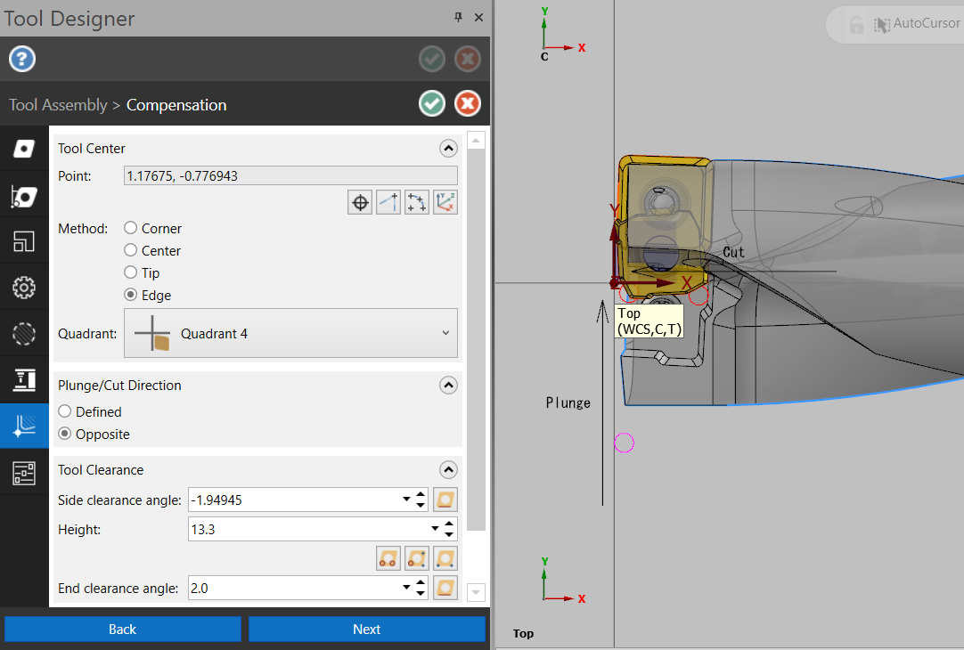
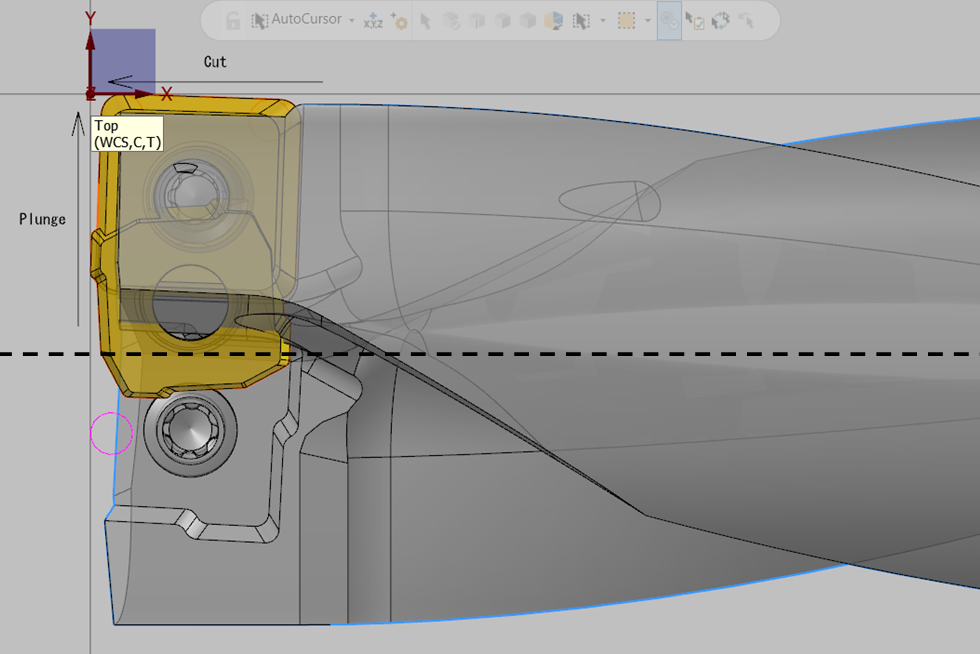
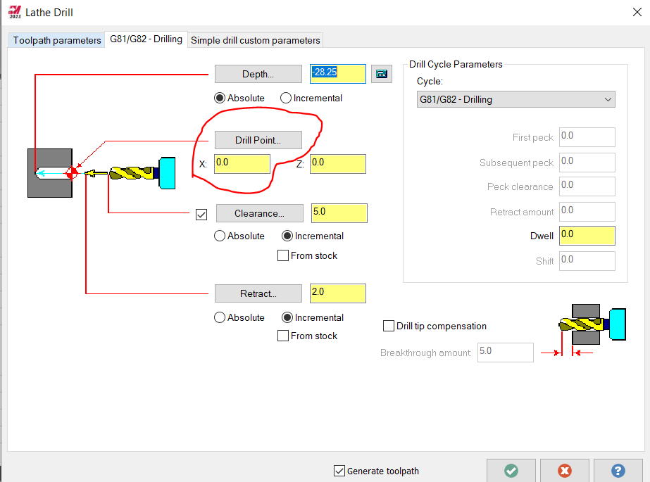
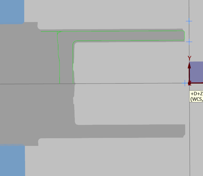
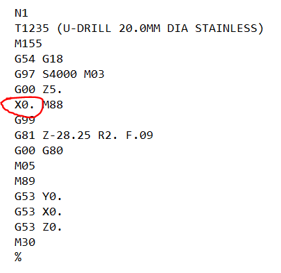
Thanks guys, I had a crack at the Multi-function type for the drill, but couldn't get it to do what I want. I appreciate the tip on the point-to-point operation, but I think it's somewhat too advanced for the newbies I'll be training. I'd rather use the "Lathe Drill" operation if possible. I think I fixed it though - I set up the tool side and end clearance with the drill off center, then moved the STEP file on center using the "Fine Adjustment" option in the Tool Assembly -> Compensation tab. I can now leave the drill point on center in the "Lathe Drill" op, it seems to simulate correctly, and it correctly outputs X=0 in GCode. I hope this helps someone

-
Good afternoon team, I'm fond of using my insert drill (u-drill) as a boring bar in my lathe, but am struggling to get this to work properly in MCam 2023. I have found this forum post from 2017 which suggests some workarounds, but they also suggest that the functionality I'm after is "in the works". I'm happy enough to use two offsets to define the drill centerline and the outer insert edge, but the 3D tool designer does not seem to have an option for drills, and the 2D tool definition does not seem to have the option of a custom drill definition (for the non-straight cutting edges created by the udrill inserts). I have defined the udrill as a boring bar in the 3D tool editor, and I can use this in the "lathe drill" operation with an X offset of 10.0mm to produce the correct simulation; but I then have to mod the output Gcode to get it to output the appropriate X value. I'm trying to set the program up for newbies, and I don't want them messing with GCode. Is anyone able to make a suggestion for me please? I'm not sure if I'm just missing something really simple or not.
-
A little background: Our business (~5k employees) has a policy of allowing any engineer who wants to to learn CAM to do so, so that we are able to design products and equipment better. We predominantly use 3 and 5 axis mills. I'm trying to set up MCam lathe in such a way that engineers from a milling background have a minimal barrier to entry to programming the lathe (yes, I anticipate my poor ST10Y will be destroyed by the end of the year). I have experience programming the ST10Y lathe with HSM Works (including axial and radial milling drilling and tapping, bar pulling etc.) but I am still learning MCam. I'm in the process of setting up a tool library for use on the lathe. The milling tool libraries are each set up for a different material and maximum spindle speeds, e.g. one library for aluminium, one for steel for a 12krpm spindle; one library for library, one for steel for a 30krpm spindle. Although I know I can use multiple cutting definitions for each insert on the lathe, I'd prefer not to since other engineers are likely to forget to select the appropriate material for every toolpath. We have (at present) two static ER16 collets on the turret of the lathe for holding drills, taps and reamers (pocket 1 offset 40, and pocket 3 offset 41). I would like to generate a set of drills from Ø1mm to Ø13mm in 0.5mm increments, for each pocket, for each of 3 ISO material classes (aluminium, stainless and steel) so that the lathe tool libraries are as similar to the mill tool libraries as possible (and don't require editing by others). This involves generating 26 drill sizes x 2 pockets x 3 materials, or 156 different tools to start (not including taps, center drills, spot drills, reamers, live tool milling cutters etc.) I'm not hugely excited to generate and validate all of these drills manually. It would be trivial to create an excel chart (or .csv file) of geometry and cutting parameters for the drills, Does anyone know of a means of getting such a file into MCam as a tool library? Thank you in advance for your help.