


berntd
-
Posts
17 -
Joined
-
Last visited
berntd's Achievements
")


-
Here is the requested file. The project .mcam file is under the work_folder_A directory Thank you so much Key Shaft2.ZIP
-
Don't worry, I discovered it is a Zip2Go. It is coming...
-
Heloo, Sorry but what is a Z2G ?
-
Hello, I have a small lathe of type Sherline 4410-CNC. This for my own educational purposes mostly. Like this: https://www.sherline.com/wp-content/uploads/2015/07/8400_pic.jpg The library for 2018 has a lot of lathe machine definitions included but none seem to have a spindle on the left and toolpost at the front and to the right of the spindle. The defined tools also all seem to be made to come in from the rear. To work around this, I tried turning the whole machine setup around and have a spindle on the right but tools coming from the rear. Should be the same as a spindle on the left and tools from the front). Generating any toolpath results in the tool starting in the stock error or in the chuck error or the path just does completely weird stuff that I cannot follow. Is there a suitable tutorial that I can follow to get this working perhaps? I have also included the file I am working on. Any help, as always, greatly appreciated. Best regards Bernt Key Shaft2.mcam
-
Ohh really? that will great! I saw something about tabs but had no idea that is what they are for. I will investigate and if that fails, then that may become my next question Best regards Bernt
-
@#Rekd™ Thank you very much again! I learn a lot from your videos. The toolpath seems fine now. I already made one part on the previous version of my file (after your previous help) but then as the part broke out of the sheet, the little slot was not yet milled all the way through and on top of that, my only 3/64" endmill broke. That is why I decided to change the toolpath and as soon as I can get another endmill, I will attempt version 2 of the part as per this later file. Best regards Bernt
-
Hello again, I am making progress but have hit another small hickup that I can't seem to solve on my own. For the same part as previous, I have split the geometry so that the outer contour doe snot include the tiny slot as I found that problematic during milling, Problem is however that instead of ramping clockwise around the outside of the part, the operation reverses every time it hits my added geometry. What did I do wrong? File is attached and it is the last toolpath named Outer Edge that has the problem. Thank you very much again for any help. Best regards Bernt Centre piece_2_experimental1.mcam
-
It worked!! That is not (in my opinion) intuitive and I would never have discovered that had you not told me. Thank you again. Let me see if I can make that part next... Best regards Bernt
-
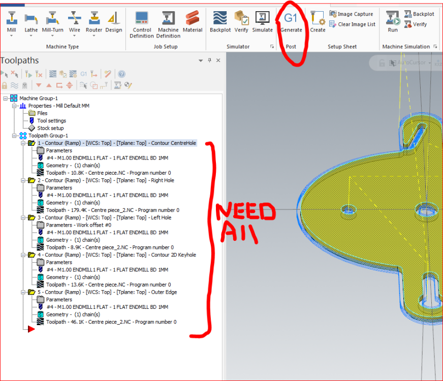
One more question about G code generation... Thanks to the help here, I have managed to create suitable toolpaths for the whole part. I now want to generate G code. Whilst that works, I am not able to get it to generate a file for all my toolpaths combined It will either just do one my paths (if I highlight it) or some weird number of paths but not all of them. How do I tell it to do them all? I am expecting a single .nc file with all the paths in it. (The tutorials I have now seen just do a single toolpath) Centre piece_2.mcam
-
Thank you that is very helpful as I know about 0 of Mastercam and have been figuring out and googling every single thing I tried to do. Best regards Bernt
-
Hello, Man, I do not know how to thank you enough!! I really really appreciate that you took the time to do that for me. It is a great video. I will re-study it over the next few days as there is a lot of valuable info there. In my original, I did try using that edge of the hole but I could never get the tool to step down on the Z axis. It just went is a circle and that was it. But in your case, it does mill down so I will study that closely how you did that. Thank you again for the great help!!! I will report back when I have it working. Best regards Bernt
-
Thank you. I did see that it has 2 chains when I did a chain analysis but as mentioned, I was not able to delete one or select the hole surface edge such that tghere woudl only be one chain. The other (correct) hole had the same issue but for whatever reason, it suddenly seemed to fix itself. I do not know how or why but it did. How would you say one can unselect or remove that second unwanted chain? Best regards berntd
-
Yes, I have set that up to be 0 at the top of stock and -2mm at the depth, see file. Yet it does not produce a toolpath past o based on the hole edge and if using the hole surface, it produces incorrectly 2 paths as mentioned. ???
-
I have tried that already but then it I can't get a depth toolpath into the material. It just creates a path in a correct circle but with 0 depth. I am not sure how to manually tell it to go down into the material based on an edge alone. ??? Best regards Bernt
-
Ok, thanks. But now how fo I get the problem fixed with the incorrect toolpath(s) that mill on both sides of the selected hole edge?


