JFGuffie
-
Posts
9 -
Joined
-
Last visited
Recent Profile Visitors
136 profile views

JFGuffie's Achievements
")


-
Thanks Aaron.. That was what I was looking for.. Very helpful to see how to do it correctly.. Sorry, but I'm sitting in Europe, so our time zones are quite different, that's why I first respond now..
-
The file is attached heSample.mcamre.. I removed the rest of toolpath, since it makes it very heavy...
-
And with Unified, it doesn't look any better..
-
Was looking for that too, but can't find it in 2023?.. From what I could read it was replaced/merged into Unified, but can't get that to work..
-
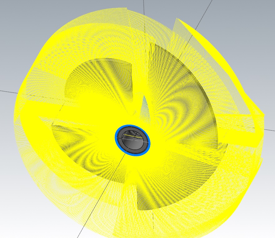
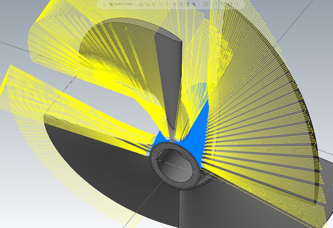
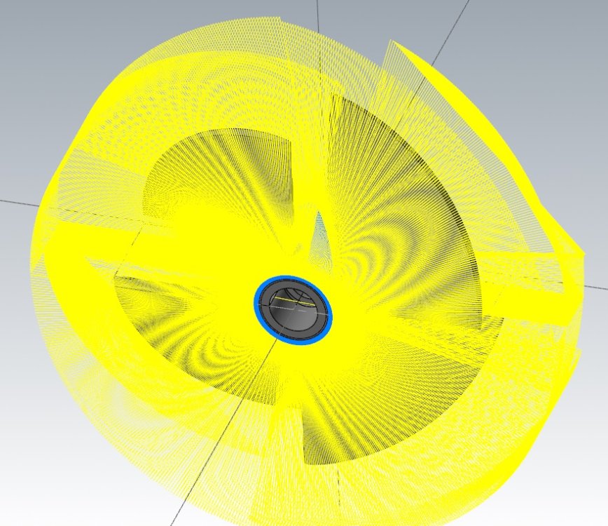
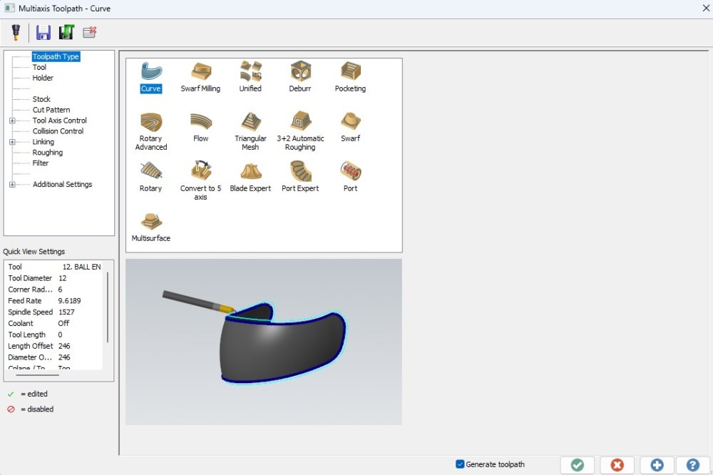
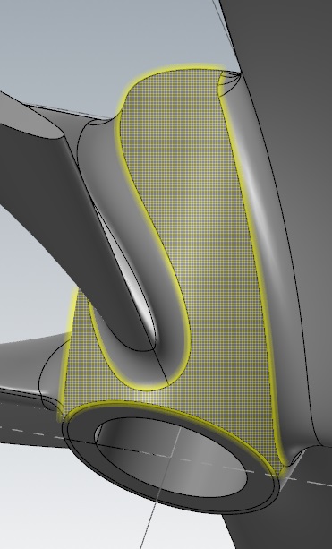
Hello I have been struggling to optimize this item, since no matter what kind of toolpath I'm trying to use, I have a lot of rapid retracts, which is time consuming.. See pictures here below.. Does there exist a 4-5 axis toolpath, which can make all bottom surface just following the bottom surface, without retracting all the time.. I have tried "Rotary, Rotary Advanced, Unified, Flowline and can't get anything better than example here below.. But I'm far from expert in 5-axis toolpath, so maybe some of you guys have a better suggestion..

-
Sorry for not responding before, but was out of office end of last week.. Thanks for the help.. It has been very helpful.. I see that I still have a lot to learn..
-
Thanks for your input.. The machine has just passed one year of age by now and is a Smooth AI.. I'm running with G61.1 followed by a P6.. I have tried to change to P7, which should make more smooth surface.. It also runs more slowly, but it just increases the steps everytime it slows down.. Below here in an example from the output.. Maybe that will help to explain something.. :) N3 (OPERATION 3) (Ø16 R2 BULLMILL LONG) G0 G90 G18 G40 G49 G80 G69 G10.9 X0 M200 (1ST SPINDLE MILL MODE) G17 G54 T#501 M6 T#502 M821 (ACCURACY LEVEL) G61.1 P6 M108 (UNCLAMP B) G90 G0 G53 B95.1 #150=#3020 #151=#[60000+#150] #152=#151+170.2 #153=-46.275-[#152-#152*COS[95.1]] G0 G43 Z#153 M212 (UNCLAMP C) C194.125 M8 G97 S12000 M3 G94 G43.4 X139.269 Y-7.763 Z-46.275 C194.125 B95.1 X66.558 Y-7.763 Z-39.785 C194.125 B95.1 G5P2 (HIGH SPEED ON) I'll contact my local Mazak guy and ask him acc. to what you write.. Maybe he can check up on something, since I have no experience with G61.2 and how to use it..
-
Thanks for your suggestion.. I didn't thought about the difference with a bull or ball.. I just assume a radius was a radius.. The feedrate was just to speed up the test itself.. I tried with half the feed and surface still didn't appear better, when it comes to those "steps" in the surface.. I tried to make it as one all the way around, but due to the top and bottom, but couldn't get it to work, probably due to the geometry of the blade, which is strangely curved in the bottom profile.. I have played with filters, but in Mastercam and on the machine as well.. It has several options, depending on what type of machining you do, but that didn't help either.. I have made some test since I posted this with the Unified tool-path, and it actually looks quite much better.. Not perfect still, but maybe with a ballmill I will archieve what I was hoping for.. I have already played with this as well, tried everywhere from 0.1 to 1mm in Angle increment.. Generally the more smooth I program the toolpath the worst it looks on the machine..
-
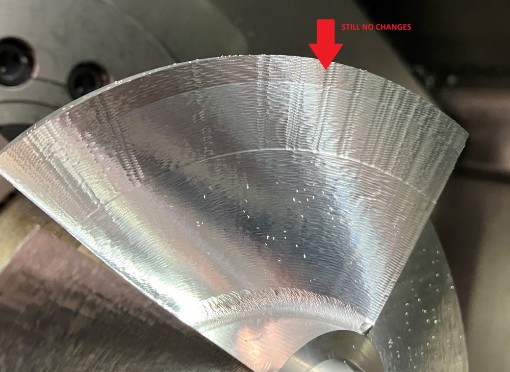
Hello I'm programming and running an impeller on a new Integrex 250 with Smooth.. I have some issues with getting nice surface quality.. I have tried many setting, spoken with my Mastercam reseller as well as Mazak for finding optimal parameters etc.. The weird thing is that I get a better surface with more rough filter and cut tolerance, compared to when I choose to remove filter and go with very narrow cut tolerance.. But both of them doesn't give me what I expected.. I have attached my program as well as a picture of a finished wing.. The upper part is done with fine cuttingt tolerance and no filter.. The lower part is done with more rough tolerance and filter as well.. The red arrow just refer to a finish, where I have move the tool 0.01 to ensure it wasn't tool deflection that caused the problem.. Can anyone help to guide me in which direction to go, maybe different type of toolpath or something to get a better surface finish? Thanks Impeller.mcam