


GeoGirl
-
Posts
38 -
Joined
-
Last visited
Content Type
Profiles
Forums
Downloads
Store
eMastercam Wiki
Blogs
Gallery
Events
Posts posted by GeoGirl
-
-
Damn it, just like that its done. OMG the time I spent with this. And I've done this type of profile before. I just didn't have the chains going in the same direction I guess. UGH
Thank you so much!!!!!!!!!!!-
 5
5
-
-
Thanks mwearne,
I'll work in it in the morning and let you know!
-
Hi Gang,
I lost my solidworks availability so now have to draw/model in X9. I don't have to create models too often and I am struggling with what should be simple. The attached file you will see the shape of a rail - yup train rail. I have to make a transition from a new rail to a worn rail... the top is 14mm lower. So just somehow extrude from one to the other. Solid form. Why is this so difficult for me? Ignore the simple circles on the file,, I was trying to figure it out.
Please help, maybe I can buy you a coffee or donuts! -
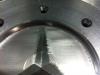
I checked and my machine has look ahead (I thought so, its only a year old). I re-ran the program, just the star section and made the toolpath travel along the star and you can see in the picture what happened. Again I just reran the program .005" deeper. But I still don't believe gouging should behappening right?
-
Sorry for the delay all. Other jobs are a priority over this one. My controller is a Fanuc oi mc. No jerky movement with directional changes. The only reason I was using a .002" depth of cut is because I am just recutting the current part instead of making a new one every time. There should be no gouging from previous operations since I have rerun this too many times now
.gif) I am cutting it one way and still having the same problem, but a little less. I have added a new photo and the witness line you see as a circle mid way around the star is from the tool path hitting a previous cut section.
I am cutting it one way and still having the same problem, but a little less. I have added a new photo and the witness line you see as a circle mid way around the star is from the tool path hitting a previous cut section.This last tool path was using the advice from MotorCityMinion using the SF blend.
Any other suggestions are still appreciated. I should have more time this week to play with this and actually act on your advice.
Thanks
Geo

-
Actually both machines are new within the last year. Both Fanuc controllers. and we are not a real production shop and these machines not used "hard".
Are both the machining centers you tried it on anilam crusader M's?
Just kidding but it isn't out of the question that 2 mills in the same shop could have similar z axis problems especially if you use them for a lot of peck drilling.
-
How do I put a copy of my file on the FTP?? Do I post my own drop site for people to access? or is there a place for that here?
The only reason I have been making a finishing pass of .002" is because I just try to rerun this part so I figured .002" should eliminate heavy chip loads (to rule out problem one)
I would leave at least .01 material for the finish toolpath. Even with a .125 Ball Endmill, you need to have some material left over for the tool to cut.
Can you put a copy of your file on the FTP? Someone here I'm sure can help you with an example toolpath.
Personally I would use MCM's suggestion and do a blend toolpath, using a circle and a point in the center, with the spiral option turned on. I would use a tolerance of .0001, and use the filter settings to fine-tune the path.
-
What kind of feed rate should I be running on this clean up pass, spindle 9000???
-
Here's how I might do it. Fill the star (suppress it if created in MC) then use the HST Spiral or SF Blend to finish the circle. Independently finish the star with SF blend, which may require several operations, or... yuck, a scallop path if you want to get it in one op. If at all possible, extend the surface edges of the star up above the circular face to use as a smooth lead in for the cutter and help to avoiding rolling over the edge and ruining the definition of the shape. Choose a blend direction that goes along the length of the points, not across. Your blend chain may look like an arrow with a point in the center of the base. (3 entities). Repeat for the other 2 legs of the star. One way cut if possible.
HTH, MCM
wow, your explanation I think is quite over my head!

-
I am using surface finish parallel, have tried a few of the others, can't remember now if I even tried to run any of the others. Is there a preference with this type of profile?
-
Hi gang,
Looking for a little help with surface finish. I tried to upload it to an album I created under my name, but its not working... maybe in an hour there will be 10 of the same pics in there!
quick description
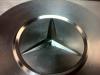
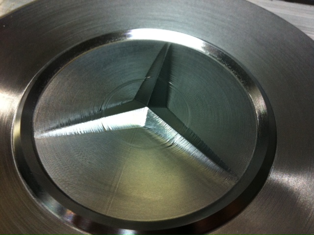
aluminum part. kinda looks like the mercedes/polaris star logo. The total depth of the star is .100" and part is only 6" in dia.
I am roughing the part with a 3/8 ball end mill and finishing with a 1/8 ball end mill. I even switched to a different machining center to verify it was not the machine. My finishing pass is only .002" depth. I want as smooth as possible, but I am get sort of a galling or gouging effect when the shape meets the flat bottom surface. I am now running this part on a 10,000 rpm spindle. I know not much compared to what some of you guys have, but it should be able to do the job. I hope my image shows up in my album so you can see what is happening. Unless there is another way to upload a photo to this question.
I have tried almost all of the surface finish features, but it does not show up on the screen. I have to run it to find the problem.
Hrumph!
I am using Mx4 (oh I found a way to attache the file!)
Look forward to your help
Geo
-
maybe its because I could only plunge the first insert. My cutter must have been too big. I had a 1.5 dia and the wall I had to machine away was .300, so I tried a .125 step over. I have never seen anyone plunge mill, but it sure was sure loud (maybe thats normal) Maybe I was to chicken to feed harder. I have a huge job that will require plunge milling in the next month, our tool supplier suggested the tool and it is using the same material. I will post another question when I can apply it to this particular job. I will go back and see what I was trying to use as a feed and rpm. I then tried to use a rougher with no luck. Never tried a rougher in steel, but it was bad.
-
I did not get it to work :-(
-
Oh, and what should my step over be? I was thinking .125, but I'm just guessing :-)
-
Hi, with all your help I think I will be ready to try this in the morning. Any suggestions on feed and speed? I have an Ingersoll 15s (2 flute 1.375 dia, one insert on the outer edge, the other in the center to drill a blind hole) The center hole is there and I have about .800 along the edges of this pocket (kinda of an oval shaped pocket) to remove. Material is 4140 HTSR. If I am reading the charts right...the RPM should be 1450 - 2320, fr 7 - 18. (I used the formula based on 1 insert, should i be basing it on 2?)
TIA
GeoGirl
-
Thanks gang,
I have enough to play with now, not sure if I grasp it all, but will give it a try.
Thanks again
GeoGirl
-
Hi gang, I try not to post here much because I am so green. I want to plunge mill a ring 1 inch deep and I have the right tools. I did a search here, but kinda need more help. Do I have to create a surface first? The only plunge operation I can find is under surface plunge rough. Is there other ways? When I try to use a surface it asks for a grid and I'm not sure what that is. Sorry to be such a pain, but the help files are no help.
:-(
TIA
GeoGirl
-
Hi again,
Thanks, Micheal got me out of the emmediate bind, later today I will play with the facing.. I know I did change the y value once, but it didnt' work, had to be my mistake.
I'll let you know how it works out!
Later, and thanks
Geo
-
Hi Michael.. you had the correct answer!
That is exactly what I want, would have never figured it out. I tried in the face command, changing the approach, but it was approaching in the X and I need it to approach in the Y.
You guys are the best.
Geo
-
Hi guys,
C... I don't need to ramp, just need to find a way to enter off the part. If it meant I had to ramp I can do that. Don't know if I have to use the facing command or pocket. I just know its fighting with me. I am fairly new obvioulsy, I will try the open pocket again, just not sure how to work with it. What toolpath should I be using to "selecting a point before your geometry so the tool starts from that point"?
You guys are such a great help
thanks again
Geo
-
Hi gang,
How do I ramp in from outside of my part using say a 2 inch face mill. I can't plunge ramp, I need to come in off the part, but only in from 1 specific edge. Do you have to draw this profile in to create the toolpath? Struggling
Thanks
Geo
Using X now :-)

-
Colin,
i have no idea.. I will have to ask my boss.
Thanks
Geo
-
wow, I have never heard of "transform op", now I have alot of reading to do. Do you still draw all your parts, and just use the "transform op" for your toolpaths? Haven't had a chance to try it yet.. so I may be waaaay off.
Thanks again
Geo
-
Hi, I think I approached threadmilling all wrong. My tool was just a 1/2 dia cutter, but I put in all the tool data when I picked the threadmilling op. Guess I should have created a tool huh? Which is better, creating a seperate MC9 file or as a level on my part file?? Which I have never done by the way :-)
Thanks, and yes, we have thought of upgrading, the timing is just not right :-(
Thanks again
Geo


Plunge milling a pocket
in Industrial Forum
Posted
Hi gang,
Ok, I have a steel block 12" x 20" x 5", and a large bottomed hole about 4.7" deep for a bearing about 9" dia (has a through hole about 7" dia).
Right now I drill through, then end mill large enough pocket for my face mill and have to do this in steps. Thoughts on plunge milling the hole. When I say plunge, I mean milling in the Z, not ramping. I have a 1 1/2" dia 3 insert plunge cutter that is plenty long enough. Is this wise being an internal pocket? I don't have air, can only blast with coolant. Can Mastercam create a plunge pocket op for me?? Using Mastercam 2019.
Thanks
Georgette