


mikechvz
-
Posts
131 -
Joined
-
Last visited
Content Type
Profiles
Forums
Downloads
Store
eMastercam Wiki
Blogs
Gallery
Events
Posts posted by mikechvz
-
-
It depends on setting 33.
Do you have probing on the machines?
If yes, the G52 will not be a global offset to the other work offsets because setting 33 is Fanuc. When the reset or cycle start buttons are pressed, all the values ins G52 will go to 0.
If no, change setting 33 to Haas and G52 will hold the values and apply the values to all of you other work offset.
Setting 33 can also be Yasnac, and G52 will be another work offset like G54, G55, etc.
The inspection plus macros supplied by Renishaw require that setting 33 be in Fanuc mode.
Kind regards.
Clarence
no sir we do not have the probing on this machine, and I do not want the Yasnac settings.
is the difference between HAAS and Facuc setting in 33 just that the fanuc setting goes back to ZERO in the offsets?
-
howdy
for the past 8 years ive only worked on DAEWOO and DOOSAN machines with FANUC controls of course. I recently took a new job, and they have all HAAS. When I used the FANUC there was G54, G55, G56 etc.Above my G54 setting was a "shift offset 000" where if I wanted to offset my Y +.010 all I had to do was put .010 into the y coordinate instead of adding +.010 into the G54 and changing my TRUE origin. On the HAAS I see there are G54 G55 and so on, but also a G52. do I have to change my actual G54? is there a world coordinate offset that I can make incremental offsets instead?
-
restarted computer, things worked out
-
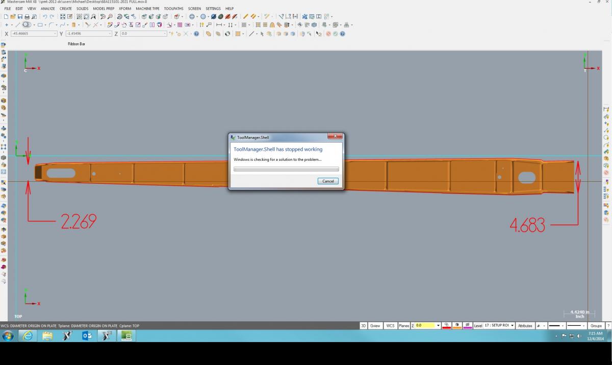
opened a file that ive been working on for a few days with no problems at all, and then....
-
it was the 'workspace' that got changed. Every toolbar was open and all keyboard shortcuts were turned off, just defaulted it back and all is well. Don't know how or when that was changed, but its new to me, and now I know. Thanks guys
-
im setting them myself in Customize, I didn't know there were none set.
When I press F9, im not getting my origin to toggle on/off , does this need to be setup too?
-
just had our IT help with an admin install/upgrade to X8 . im setting up some custom colors and my mouse settings, etc. but all the normal key moves like alt+s and alt+a etc. aren't doing their commands, theyre just opening the solids and analyze dropdowns from the top toolbar.
never have had this issue with the other versions. Suggestions?
thanks in advance
-
It looks like a weldment. Is it a weldment? If it is couldn't you make the seperate pieces, put the holes in, then turn some shatfs to hold the plates in the appropriate posistioning while it is welded?
that would work, but no sir, its not a weldment
-
lookin into this, thanks for the link
-
.010 tolerance on diameter
baseball bat sounds like the solution tho, thanks
we looked for a angle head bit trying top find one small enough for the length
-
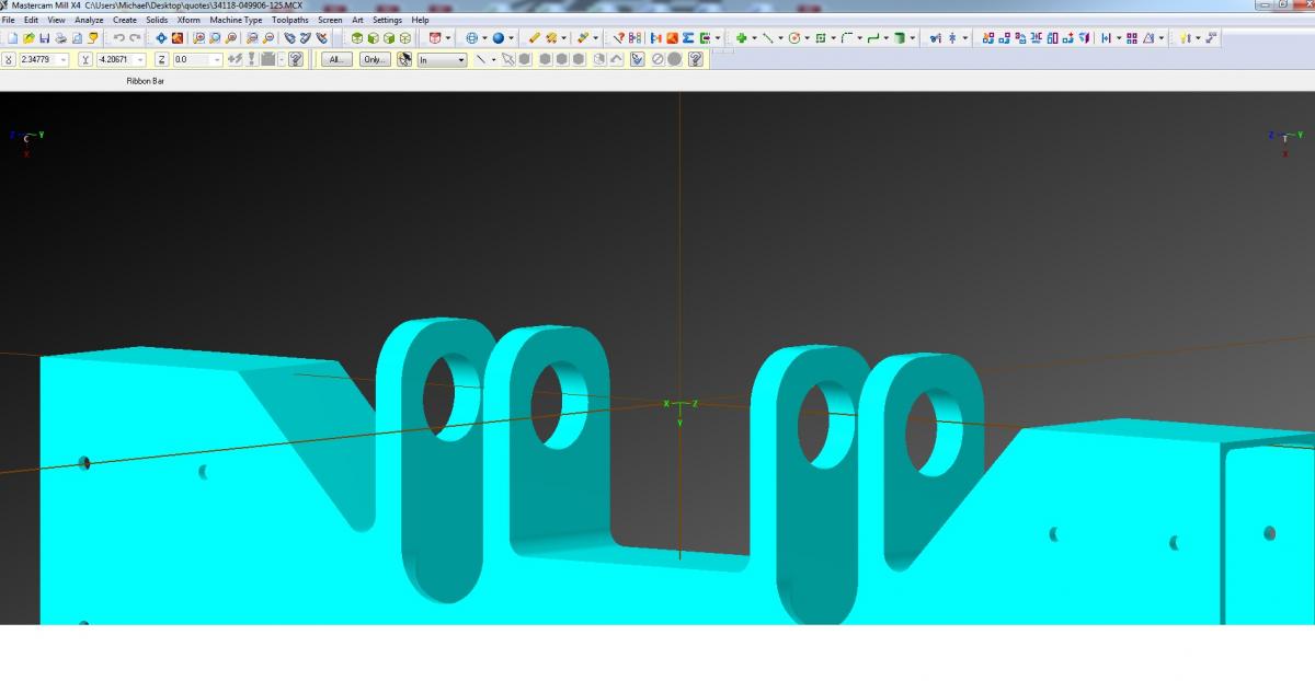
those 4 holes are 1.160 dia. the 2 center ones are spaced 4.0 inches from each other edge to edge. ive worked on holes and bores that were partially blocked but they were very small diameters and it wasnt 4 that need to be concentric.
Does anyone have a tool/setup suggestion or experience with something similar.
the 2 outer holes are also partially blocked by the 45 degree wall nexto it also
thanks in advance

-
we use a KENNAMETAL NPT thread mill insert with a KENNAMETAL NPT tapered insert holder. i set to the major diameter and work my wear offset into that, it works great when we start from the top and thread mill helical from top to bottom. Last time we ran this tool, it was on a brass job for about 3000 parts with 3 different NPT outside threads, and we only had to offset it a few times by tenths .000x
-
our trim-sol was horrible. got the boss to switch to Chemtool Incorporated and have never had a problem again
-
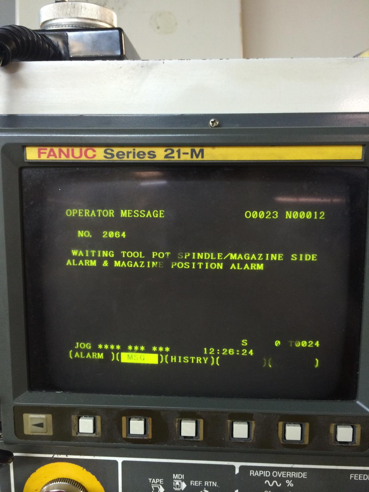
the carousel had moved some, just had to push it back in and get the sensor and limit switch into positions. thanks for the replies, always appreciated
-
its not the upright perpendicular tool changer, its the older carousel style changer where the tools are in the same position as the spindle
-
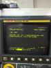
idk if im asking this in the right forum, but has anyone else experienced this alarm? Just re positioned our machine in the shop this morning, and when we powered it back on, i cant reference the z axis.....
-
@Thad and @FROZEN thanks for the reminder
-
its early and i cant think. just received a file from a customer and upon opening it, the popup box said its converting units from standard to metric. what can i do to get back? thanks in advance
-
space claim does wonders
-
 1
1
-
-
+1000
Also, how about the ability to change the text color in the operations manager using individual colors. Some of my files have 300 operations and sometimes it would be nice to designate what operations are roughing vs finishing, and so on using different colors.
now this interests me
-
Rickster and Crazy^Millman thanks a lot for the lesson
-
if you cant allow for a .005" rad then you are out of luck, as
solid works and space claim can only get a .27 rad with out erroring
put the .005 rad in and it can do it
space claim allow's you to remove the .005 rad (SW does not)
Do you want an .stp file of any of these?
this one with the edges instead of the rad is perfect. Space Claim? im unfamiliar with this
-
if you cant allow for a .005" rad then you are out of luck, as
solid works and space claim can only get a .27 rad with out erroring
put the .005 rad in and it can do it
space claim allow's you to remove the .005 rad (SW does not)
Do you want an .stp file of any of these?
man THIS right here is exactly what i need!!! thank you sir, and yes please
-
i just uploaded a file to the X4 files folder named 'Radius Challenge".
i marked all the edges in red that im having difficulty with. They all need to have a .313 rad, but i cant get them to work together? any help is greatly appreciated. Ive tried a few different ways but its to the point where i think im confusing my self somewhere. thanks in advance, any suggestions?
HAAS offset from FANUC
in Industrial Forum
Posted
this is exactly what im talkin about. thanks everyone, great help