


Mic6
-
Posts
1,141 -
Joined
-
Last visited
Content Type
Profiles
Forums
Downloads
Store
eMastercam Wiki
Blogs
Gallery
Events
Posts posted by Mic6
-
-
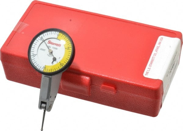
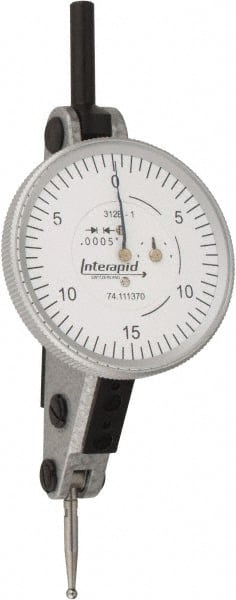
Yea, I think it's time for an upgrade. The Starrett feels like a featherweight compared to the "heavier" Interapid.
-
 1
1
-
-
I've been using the Starrett for the past 11 years with zero issues, but I'm told to pick a new one so I'm torn between the Starrett and the Interapid. Does the Interapid require less stylus pressure? Especially for dialing in spindle probes? Is the Interapid stem removable?
TIA
-
The 2:00 minute mark!
-
-
Hey Guys, I've been threadmilling a lot of parts and in my thread data printouts I have a wire size, say Ø.036 and a MOW of 4.3984 to 4.3925. Since my wires are the "gauge", would it be better to stay in the mean of the range, away from the "no-go" low end?
-
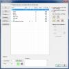
I'm trying to download it, but it tells me I need to make a purchase? I'm at home so I don't have my mastercam.com linked account. Little help?
TIA
-
Various reasons that would require another thread.
So far I've gathered that these are pretty good machines! Is anybody running them in a 3+2 configuration with full 5th axis? If so, what brand trunnion/rotary are you using and how easy is the interface?
D500
.gif)
-
I run a carbide shank with a .07 ball from Q-mark.
-
Under Finish Lead-In/Lead-Out, do you have Tangent selected?
I would rough it all out, leave .002 on floor and wall for Finish
-
 1
1
-
-
I do a higbee on the mill all the time in 4-16 threads as well as 10tpi Buttress. I draw a single helix and dynamically rotate it to align the start with the threadmill start point.
-
And you probably only had one of those thread mills huh? What kind of machine was it?
-
Thanks Ron, it's blocked here, but I'll download from home.

-
I know I could make it, but I was wondering if anybody had1 available. TIA!
-
Be careful... you have Y.050 in that plane as well... just make sure that's what you want.
Also, it really doesn't matter if you use inc or abs... really preference.
My preference is to use inc as much as I can... that way if I need to move something later, my linking settings will move with my geometry.
Thanks Reko, Ijust saw that .05 in Y, that would've sucked. In regards tot he outputted cod I have my Z set at COR so I could work with 1 offset. Looks like I programmed it wrong and have to go back and pick heights with everything set at Top/Top/Top. If I do this, how will MC know to post A rotations? Or, to save time, just leave it as is and set each face with it's own work offset?
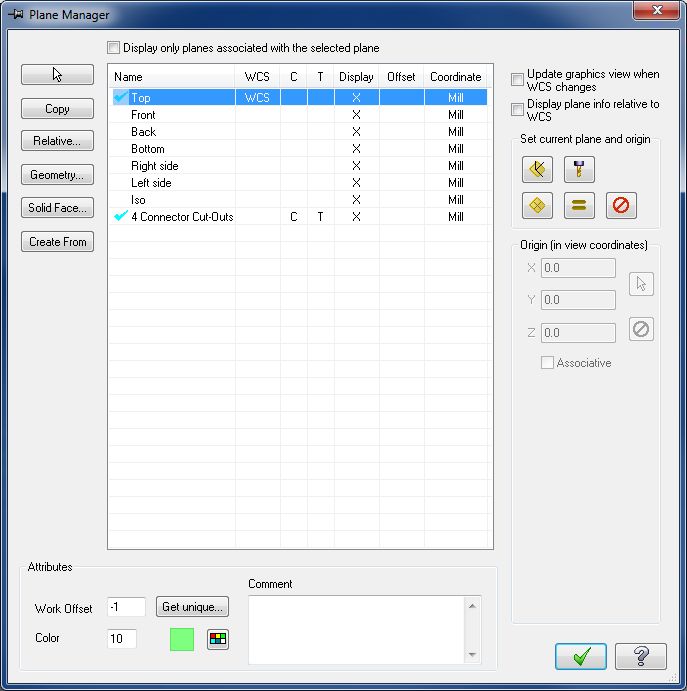
If you have setup the WCS to be on COR then the output will come out that way. You have set up a Tool Plane that is above COR then you don't want to work from COR you want to have a workoffset for each face and will have them set in the machine. If you want to work from COR then your Z0 must be from COR and then your programmed values will adjust to that Zero. You have setup a method that will have you setting a Z for each face and not one Zero for all faces. If you take what you did and change the T and C plane to Top and post the code you will see they are relative to COR. If you have set Zero on the machine to be that face then you have gone about this wrong and will need to decide if you want to work from COR or from the Faces which are 2 different things all together.
Yea Ron, I want 1 offset to run at COR. When I changed everything to TOP, the code looks good relative to COR. In what instance would I use TOP=TOP T/C= named plane? Is the point of creating a plane at each face to get the rotation code?
-
Hey guys, I have an electronics enclosure 6.00 x 7.00 with cutouts on all sides. I have it setup on the indexer, with center of rotation in Z @ TOP and the part surface is @ the "4 cutouts" plane. My output Z zero keeps going to COR. I included a sample file which shows just 1 side. I have 4 sides programmed already and I know the A-axis output works, and even shows perfect in verify. Is it best to program all my heights INC when doing rotary work?
-
1
-
-
Fadal. That way you can throw it away when you are done.

Pretty much
-
Hey Ron, well I got it to work and update my offset. No production here, just 3 electronic boxes, but I just wanted to practice probing and to save my self some indicating. I loaded my part onto pins at A0, ran an indicator across to align it, and set A0. I ran the probing cycle and it made an update of .004 degrees. I ran the indicator end to end again and it moved somewhere with a .0001 hashline
Works for me!I've seen other probe cycles online where the probe moves to position in Y+, the part rotates until it hits, the probe them moves in Y-, probe takes another hit and then sets zero at the flat. Is this a custom cycle or another MTB's?
-
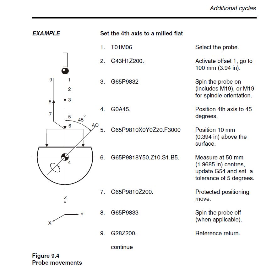
Thanks for replyin Zoob. I totally missed the A0 position in the pic. So in my case, I would leave A at "A0", and run 9818. I don't see any A moves in the example, are those in the actual macro?
-
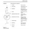
Hey Guys, I have a 4th axis part I want to automate setting the flat. I'm a bit confoozed. In the Renishaw Inspection Plus PDF, pg 9-9, why does the example rotate the part 45 degrees before any probing is done. If I have my part on a fixture which holds the flat parallel to the table, can I bring the probe in, move in Y3.0, hit, move Y-3.0 hit and update S2? Can I get some clarification?
TIA
Oh this on a Haas VF2 SSYT, HA5CB
-
I've always been intrigued by that. Turn the part and rotate? I dunno
-
I'm looking for toe clamps to hold down the said vise. I can't find them on Kurts website or MSC. I found these from Glacern in a search, but I was wondering if there is an official Kurt part #.
Boss doesn't want me to make them, so here I am.

-
Hi curious-n00b,
Could you send me a PM with your SIM number or the name of your reseller?

 No popcorn, so pizza it is!
 -
Keensert installed, chemfilm touched up. SHIPPED
-
1
-
-
I've done that before on #10 and below. 1/4 - 20's are stiff!
Machining Small Fillet with Big Endmill
in Machining, Tools, Cutting & Probing
Posted
^^YUP
or
Finish the wall to sayyy R.3, then come back and remachine and blend. Remachine rules.