Mic6
-
Posts
1,141 -
Joined
-
Last visited
Content Type
Profiles
Forums
Downloads
Store
eMastercam Wiki
Blogs
Gallery
Events
Everything posted by Mic6
-

Machining Small Fillet with Big Endmill
Mic6 replied to randommachinist's topic in Machining, Tools, Cutting & Probing
^^YUP or Finish the wall to sayyy R.3, then come back and remachine and blend. Remachine rules. -
Trying to decide on new Test Indicator
Mic6 replied to Mic6's topic in Machining, Tools, Cutting & Probing
Yea, I think it's time for an upgrade. The Starrett feels like a featherweight compared to the "heavier" Interapid. -
I've been using the Starrett for the past 11 years with zero issues, but I'm told to pick a new one so I'm torn between the Starrett and the Interapid. Does the Interapid require less stylus pressure? Especially for dialing in spindle probes? Is the Interapid stem removable? TIA
-
The 2:00 minute mark!
-
Hey Guys, I've been threadmilling a lot of parts and in my thread data printouts I have a wire size, say Ø.036 and a MOW of 4.3984 to 4.3925. Since my wires are the "gauge", would it be better to stay in the mean of the range, away from the "no-go" low end?
-
I'm trying to download it, but it tells me I need to make a purchase? I'm at home so I don't have my mastercam.com linked account. Little help? TIA
-
D500
-
I run a carbide shank with a .07 ball from Q-mark.
-
Smoothing entry and exit on pocket mill with helix entry
Mic6 replied to honeybunches's topic in Industrial Forum
Under Finish Lead-In/Lead-Out, do you have Tangent selected? I would rough it all out, leave .002 on floor and wall for Finish -
I do a higbee on the mill all the time in 4-16 threads as well as 10tpi Buttress. I draw a single helix and dynamically rotate it to align the start with the threadmill start point.
-
Machine broke my tap, then my threadmill, Arghhhh
Mic6 replied to taperlength's topic in Machining, Tools, Cutting & Probing
And you probably only had one of those thread mills huh? What kind of machine was it? -
Haas VF2 SSYT Tabel Model, anybody have 1?
Mic6 replied to Mic6's topic in Machining, Tools, Cutting & Probing
Thanks Ron, it's blocked here, but I'll download from home. -
I know I could make it, but I was wondering if anybody had1 available. TIA!
-
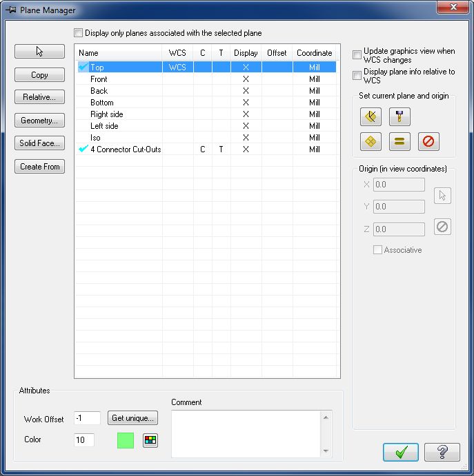
Thanks Reko, Ijust saw that .05 in Y, that would've sucked. In regards tot he outputted cod I have my Z set at COR so I could work with 1 offset. Looks like I programmed it wrong and have to go back and pick heights with everything set at Top/Top/Top. If I do this, how will MC know to post A rotations? Or, to save time, just leave it as is and set each face with it's own work offset? Yea Ron, I want 1 offset to run at COR. When I changed everything to TOP, the code looks good relative to COR. In what instance would I use TOP=TOP T/C= named plane? Is the point of creating a plane at each face to get the rotation code?
-
Hey guys, I have an electronics enclosure 6.00 x 7.00 with cutouts on all sides. I have it setup on the indexer, with center of rotation in Z @ TOP and the part surface is @ the "4 cutouts" plane. My output Z zero keeps going to COR. I included a sample file which shows just 1 side. I have 4 sides programmed already and I know the A-axis output works, and even shows perfect in verify. Is it best to program all my heights INC when doing rotary work? 4th sample.mcx-9
-
Pretty much
-
Probing a flat on the 4th axis P9818
Mic6 replied to Mic6's topic in Machining, Tools, Cutting & Probing
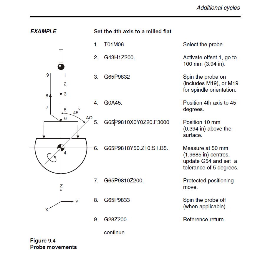
Hey Ron, well I got it to work and update my offset. No production here, just 3 electronic boxes, but I just wanted to practice probing and to save my self some indicating. I loaded my part onto pins at A0, ran an indicator across to align it, and set A0. I ran the probing cycle and it made an update of .004 degrees. I ran the indicator end to end again and it moved somewhere with a .0001 hashline Works for me! I've seen other probe cycles online where the probe moves to position in Y+, the part rotates until it hits, the probe them moves in Y-, probe takes another hit and then sets zero at the flat. Is this a custom cycle or another MTB's? -
Probing a flat on the 4th axis P9818
Mic6 replied to Mic6's topic in Machining, Tools, Cutting & Probing
Thanks for replyin Zoob. I totally missed the A0 position in the pic. So in my case, I would leave A at "A0", and run 9818. I don't see any A moves in the example, are those in the actual macro? -
Hey Guys, I have a 4th axis part I want to automate setting the flat. I'm a bit confoozed. In the Renishaw Inspection Plus PDF, pg 9-9, why does the example rotate the part 45 degrees before any probing is done. If I have my part on a fixture which holds the flat parallel to the table, can I bring the probe in, move in Y3.0, hit, move Y-3.0 hit and update S2? Can I get some clarification? TIA Oh this on a Haas VF2 SSYT, HA5CB
-
Interesting Tool Holder (video)
Mic6 replied to taperlength's topic in Machining, Tools, Cutting & Probing
I've always been intrigued by that. Turn the part and rotate? I dunno -
I'm looking for toe clamps to hold down the said vise. I can't find them on Kurts website or MSC. I found these from Glacern in a search, but I was wondering if there is an official Kurt part #. Boss doesn't want me to make them, so here I am.
-
Simple 45 Degree Chamfer on a "Complicated" Object
Mic6 replied to curious-n00b's topic in Industrial Forum
No popcorn, so pizza it is! -
Keensert installed, chemfilm touched up. SHIPPED
-
I've done that before on #10 and below. 1/4 - 20's are stiff!