


Manuel0822
-
Posts
122 -
Joined
-
Last visited
Content Type
Profiles
Forums
Downloads
Store
eMastercam Wiki
Blogs
Gallery
Events
Posts posted by Manuel0822
-
-
Thanks, Chris.
That video does actually show a lot more than the one I saw before and it does sure looks a heck of a lot easier than solidworks.
EX-WCC, that's the way I go to but was just wondering if you still had to do intersecting curves and such. Looks like the integration with GeoMagic it's working off a lot better at least for common shapes recognition and moving/aligning your mesh to the axes.
Thanks for the feedback!
-
Got it, From what I saw on the videos I thought it would do fine but now I get it. I still would like to see a complete video of it working on cloud data not only aligning a part.
-
Just wondering, Is anybody using SpaceClaim for reverse engineering I.E. scanned point cloud data or STL's? How does it compare to Solidworks?
-
Well it's really good to see it all worked out fine at the end. This is the reason I always try to stick around to this forum, there is something new to be learned everyday!!!
-
 1
1
-
-
I see what he's doing.. but I'd never do it that way
Neither would I that's why I would rather leave somebody else answer while I chill down a bit. The fall has finally made it to the south...
if you have the answer with all your rants please share..by all means...
You could compare the previously given examples or even the one Gcode is kindly giving you right now.
It only took me ***Hint 2 ***Hint seconds to finally understand his method.
IOW, check your pics
-
Really??!!! ROFFLMFAO after all this time this is the "darkest best kept secret of all times"????? LMAO.
I'm sorry if I look like an idiot but I was already feeling a little aggravated and fed up from people who just won't listen when everybody is doing their best to politely point them on the right direction.
To me it felt like I was watching somebody trying to get Wernher von Braun disqualified on his reasoning but then again this ain't rocket science, ain't it? Just 'nother dead gomn machining question.... 'MERICA Hell yeah!!!
You know what the funniest part is? Even thought there were code snipets shown as part of the answers, it sure looks like the person arguing never bother to even check them or he can't even tell the difference between them and his posted code.
What was the end result of that poll/thread about CNC Programmers needing some actual background other than a diploma?
Anybody remember the Simpsons episode when Lisa get's transferred to a different school and she no longer is the smartest and get's all depressed? I can still remember the dialog at the end when they are trying to decide whether to go back or stay:
Teacher: "So tell me Lisa, do you want to stay here and be a little fish on the ocean or go back and be a Big fish on bowl"
Lisa: "Big fish, big fish!!!"
Wasn't it Isaac Newton who said "If I have seen further than others, it's by standing upon the shoulders of giants". I know technology is changing every second but sometimes we just have to go back to the basics.
So after my rant is over, can somebody please point the answer for him??? It only took me 2 seconds to finally understand his method.
-
Even though I'm with Mike to say I'm pretty sure you're stuck in your beliefs, here goes this sample straight from Allied's threadmilling software which you can use right from their website just for the record:
(THE START POINT FOR THE AMEC PROGRAM IS THE X, Y AND Z CENTER OF THE TOP OF THE HOLE.)
(YOUR PROGRAM SHOULD CHANGE TO THE THREAD MILL TOOL AND MOVE IT INTO POSITION.)
(INSERT THIS PROGRAM AT EACH LOCATION WHERE THE THREADMILL SEQUENCE IS DESIRED.)
(THE AMEC PROGRAM WILL SWITCH THE MACHINE TO INCREMENTAL, MACHINE ONE PITCH,)
(RETURN TO THE TOP/CENTER OF THE HOLE AND SWITCH THE MACHINE BACK TO ABSOLUTE.)
(PROGRAM NAME: AMEC_TMNK0500-NPT_11202013_18656)
(AMEC ACCUTHREAD 856 ITEM NUMBER: TMNK0500-NPT)
(PROGRAM CREATOR VERSION 4.0.0)
(THREAD TYPE: INTERNAL NPT)
(THREAD DIRECTION: RIGHT HANDED)
(PIPE THREAD SIZE: 1/2-14 NPT)
(MAJOR THREAD DIA.: 0.8320 INCH)
(LENGTH OF THREAD: 0.5340 INCH)
(TOOL DIAMETER: 0.4950)
(TOOL MAJOR CUTTING DIAMETER AT THREAD LENGTH: 0.4738)
(THREADS PER INCH: 14 NUMBER OF FLUTES: 4)
(MATERIAL: ALLOY STEEL 275-325 BHN)
(SPEED: 300 SFM FEED:0.0008 IN/TOOTH MAX RPM:10000)
(NO. OF PASSES: 3)
(PASS1: 50 PERCENT PASS2: 75 PERCENT PASS3:100 PERCENT )
(INCREMENTAL PROGRAM)
(3 PASS PROGRAM)
(PASS 1)
S2419 M03
M08
G91 G01 Z-0.5429 F50.00
G41 G01 X0.0753 Y0.0753 D1 F0.75
G03 X-0.0753 Y0.0753 Z0.0089 I-0.0753 J0.0000 F3.01
G03 X-0.1511 Y-0.1505 Z0.0179 I0.0000 J-0.1511
G03 X0.1511 Y-0.1517 Z0.0179 I0.1517 J0.0000
G03 X0.1522 Y0.1517 Z0.0179 I0.0000 J0.1522
G03 X-0.1522 Y0.1528 Z0.0179 I-0.1528 J0.0000
G03 X-0.0764 Y-0.0764 Z0.0089 I0.0000 J-0.0764 F6.02
G40 G01 X0.0764 Y-0.0764 F50.00
G01 Z-0.0892
(PASS 2)
G41 G01 X0.0824 Y0.0824 D1 F0.79
G03 X-0.0824 Y0.0824 Z0.0089 I-0.0824 J0.0000 F3.18
G03 X-0.1654 Y-0.1648 Z0.0179 I0.0000 J-0.1654
G03 X0.1654 Y-0.1659 Z0.0179 I0.1659 J0.0000
G03 X0.1665 Y0.1659 Z0.0179 I0.0000 J0.1665
G03 X-0.1665 Y0.1671 Z0.0179 I-0.1671 J0.0000
G03 X-0.0835 Y-0.0835 Z0.0089 I0.0000 J-0.0835 F6.35
G40 G01 X0.0835 Y-0.0835 F50.00
G01 Z-0.0892
(PASS 3)
G41 G01 X0.0896 Y0.0896 D1 F0.83
G03 X-0.0896 Y0.0896 Z0.0089 I-0.0896 J0.0000 F3.33
G03 X-0.1797 Y-0.1791 Z0.0179 I0.0000 J-0.1797
G03 X0.1797 Y-0.1802 Z0.0179 I0.1802 J0.0000
G03 X0.1808 Y0.1802 Z0.0179 I0.0000 J0.1808
G03 X-0.1808 Y0.1813 Z0.0179 I-0.1813 J0.0000
G03 X-0.0907 Y-0.0907 Z0.0089 I0.0000 J-0.0907 F6.67
G40 G01 X0.0907 Y-0.0907 F50.00
G00 Z0.4537
G90
So if I'm not misunderstanding the program, even the manufacturer shows a taper being programmed. If IRCC I believe my Carmex rep handed me a copy of an excel spreadsheet a couple years ago that was similar to what Allied has on their site.
I have always program using the taper and never had an issue, no matter what brand threadmill I can get a hold of, right now I have programs using Carmex, allied, stellram, emuge and advent and never had any issues so I guess there is nothing left to say than to each it's own.
If you you're doing it right the way you have it, then why bother?
Allied thread milling software
Anyways, HTH.
-
Well, I guess you could post a small pc of code and some pic of the part if you're allowed to that way we can tell you what you should be getting off of MC.
BTW, Did changing from the TL to the SL machine def fix your X- values to positive numbers?
-
Are you using the GENERIC HAAS TL 2X LATHE Machine Def?
Try using the GENERIC HAAS SL 4X MT_ LATHE instead.
HTH
-
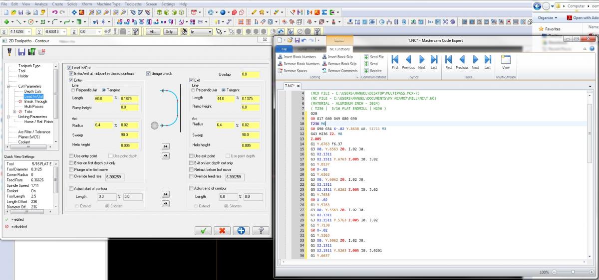
You can Try with 2D Blend, I believe that will do the trick or just as on K2csq7 file, Just shorten up your Lead out line by .05" from .1875 to .1375 and you'll get exactly what I think you want.
HTH
-
Lead in/ out for 2D contour were also added on V9.1 if IRC.
It doesn't help the OP but since we are trying to remember the good ol' times...
-
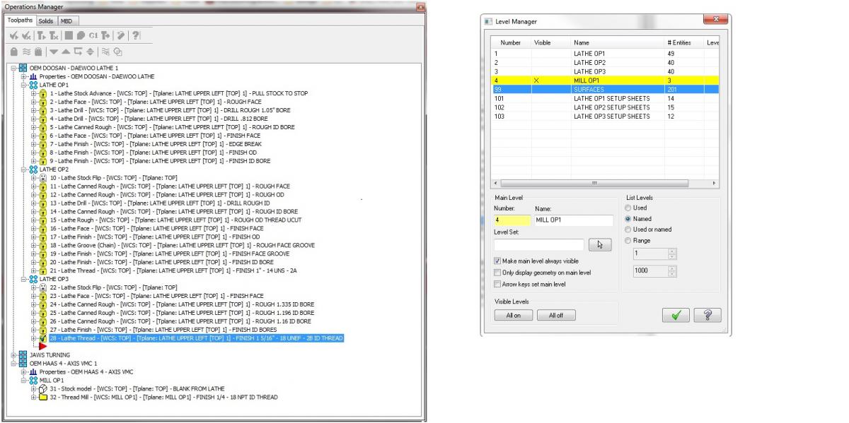
in the operation manager, over the last op right click, the go to the bottom of the tab and select lathe stock preview. select keep geometry and it will give you a solid with wire frame. I use this on every lathe program for the next operation and for my shop sketch.
^^^^^^ Same here, although all of our lathes here are the same brand which lets me just add another toolpath group for each op. I use it just as described to define a lathe blank for mill verify.
If I were to use a different machine/program format, I would do a ghosted stock flip op at the end of my 1st machine group. that way my stock for op2 would be already positioned where needed, which would make it easier to recreate stock if a change was needed on op1.
Just an idea.
HTH.

-
In the Stock Model toolpath under Initial Stock Shape instead of saying "Model" this really should say "Solid"
Well the only objection to that is that Stock Model allows to work with surfaces not necessarily only solids for it's initial stock.
I have only level one and I use it this way to verify my milling work having defined my initial stock as the surfaces saved from "stock preview" on my last lathe op. Of course this works as I try to keep only a single MC file per part number as most of what we do is really simple parts.
HTH.
-
I would also like to see this as an enhancement. Please add my vote for the change.
Another vote over here!!
Tia
-
Close the file on Solidworks!!! At least that's the solution I found when working with both, although on my case I had both on the same machine.
I found that I needed to have all configs to be regen and saved and then close the solidworks part file if I wanted the Configs to be presented for me to pick one while loading the sldprt. If you don't close it on sldwks you will always be presented the main configuration.
Give it a try.
HTH
-
Hi, thanks for pointing that out and yes, setting Z0. at top of the part could lead to crashes but in this case I'm talking about putting slots and holes around the outside of a round part, so max Z height of the stock never changes. People on this shop used to program by hand so that's the way they're used to see this kind of program.
Also when i have slots on the outside, it makes it easier for the operators to read a program where they can relate the programmed depth to what is shown on the print so I get their point on using the Z0.
HTH
-
If you always Mastercam to do it that way you'll need to change your post, just as Allan described, look for the line he mentioned on the " ltlchg postblock", pcan1, pbld, n$, *sgcode, pfxout, pyout, pfzout, pscool, strcantext, e$
and break it just as you did for the ref return block.
Or if you only want to do it on certain Tpaths, ie, you're using the tailstock, then I would just add a couple points to my chain so the tool would follow them as approach moves.
HTH
-
When you are drilling holes on the outside of a part, I like the code posted when you use the rotary axis positioning on the RA control tab, the problem I have is rotary axis positioning works the same as axis substitution, ie, your WCS has to be set to center of the part, but I would like to set my Z zero on top of the part.
Is there any other ways around this?
This is the code I would like to get:
N1
( 1/2 SPOTDRILL | TOOL - 1 | DIA. OFF. - 1 | LEN. - 1 | TOOL DIA. - .5 )
( SPOT DRILL HOLES )
T1 M06
G0 G90 G54 X-.472 Y0. A0. S1069 M3
G43 H1 Z1.
M8
G98 G81 Z-.19 R.1 F1.1
A120.
A240.
G80
M5
G91 G28 Z0. M9
M01
I know I could use transform but then it will give me a G81 line per every index position.
Any ideas?
-
Are you installing this on a user account? If you have an admin account and an user account you will want to try installing using the user login and then typing in the password for the admin account when it pops up asking to do so.
HTH
Nop, I'm the only user on this PC, I still don't understand what happened but at least I've got thru tis time
-
Thanks Scott.
It couldn't be any simpler than that. I wonder what happened this time? Have installed MC lots of times and this is the first time I've ever found this issue.
Thanks again.
Manuel
-
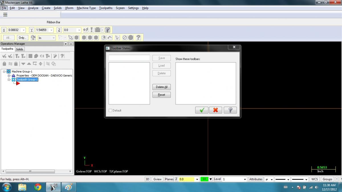
Just a got a new computer and did a clean new install of X6 on it, however after the installation no matter what i do, I will not get any toolbars, I've already tried several times removing MC with no luck, Any ideas?
BTW working on windows 7, same I had on my old PC.
TIA
-
Thanks, TK.
I guess I should pay more attention to the thread title, I can do the modeling for the looks but I was wondering if there is a way to see it like such on verify. From the threads I've found I guess the answer is no but when doing a search for knurling on the forum, this thread is the only one that mentioned a sample file.
Thanks a lot.
-
Just to bump on this old thread, and since the MC9 directory seems to be gone from the FTP, can anybody explain how this was done?
TIA
-
yep, changing it to *psgcode didn't work that's why I ended up just calling the *sgcode.
Thanks again.
5-Axis Machining Demystified - Dual-Rotary Table Mathematics
in Industrial Forum
Posted
Awesome work! Super clean explanation!
Thanks Tim!
Manuel