


Manuel0822
-
Posts
122 -
Joined
-
Last visited
Content Type
Profiles
Forums
Downloads
Store
eMastercam Wiki
Blogs
Gallery
Events
Posts posted by Manuel0822
-
-
I guess I don't follow, Are you trying to do this on a 4th Axis tilted at an angle or on a 5th axis machine? You mention the transformed dynamic is posting right, but I get it to post just as it backplots on the screen or is really that what you intended to do, criss-cross one slot on top of the other??
1st question is just since I can undertstand if you're trying to get a C & B post out or you have your 4th sitting on an angle and just want a A axis call out to be posted out.
Sorry if I don't explain myself, just trying to help here.
-
I know it's a little too late now but if you take a look at that video you posted at 0:24, you will see how the animation has a red arrow pointing up for right hand thread and pointing down for left hand thread a little later.
As just described above you need to go 1 pitch helix for multi teeth cutters and the full helix to depth for single teeth cutters. +1 to Gcode on using thread mill tpath for it.
HTH
-
Does anybody have experience on this machines?? We are looking into adding a 40" x 20" Vertical to our shop and found a machine this brand near by ready to sell but don't know anything about them.
Are they any good?
-
Just tried it here on X6 x64 and won't run either.
-
I don't know about this issue on MC but as long as it's not rotary around a cylinder you may want to check this out:
Way simpler than MCX
-
I"ve used it before with good luck although I've never done it over 12 times but I did transform up to 5 different toolpaths together and knock on wood everything it's been fine so far.
HTH
-
I wouldn't know as the only reference I have is from a shop with 1 each of Lathe, Mill & Wire so it follows your 3 seats required but my reseller didn't mention anything like that when we switch to Nethasp.
-
+1000 to Teh Bear, I never used that feature on mastercam, I'ts great to be part of this forum!! You learn something new everyday!!!
-
As long as you do remove all tools from setup to setup, you can always hit the soft key under the screen for clear all, I think I remember you would press the right soft arrow once or twice once you are on the tool offsets screen and then it will show you the key Im talking about.Once you clear them all up you should be fine to start setting up the new tools offsets.
-
You can actually ditch the holes as Hardmill Described, just take the side view and extrude thru the part, that way you can suppress/Un-suppress the feature and have a solid with both configurations, with and without holes. Check the attached file, look at the solids history and level 10 for the surfaces.
HTH
-
This my sound stupid but if you do have a network, this sounds like a good scenario for Nethasp, that way you wouldn't have to do all the hasp plug/unplug. I know it will cost but will let you use your mill or wire in any computer on the network and it will only take the license for the product you're using while the other one remains free to be pulled from somewhere else
-
Thanks Jp, That looks just like it. Having I don't have multiaxis but would like to know, Would' it be any easier with it? Will it still need quite some Geo to be created in order to work or would it just work of the solid? We are picking up on a lot of jobs with this kind of features and it maybe time for an upgrade on our license, specially if it will save some programming time.
-
I'm trying to make a profile like the one shown on the attached file but I can't figure out how to get the side walls to be straight. If I use either the Rolldie Chook or axis substitution, they will both work on Y0. while the start of my profile is at Y.75. How can I get this done without Multiaxis?? Any ideas?
TIA
-
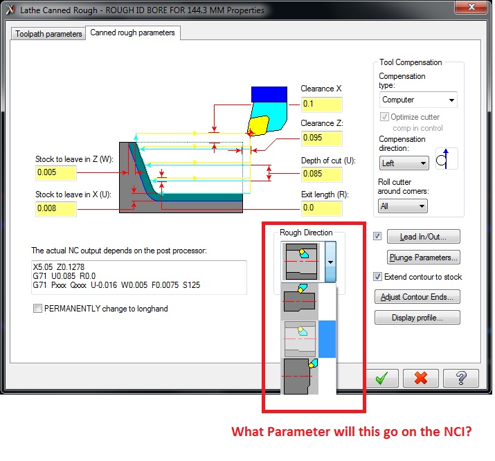
Does anybody know what flag I can capture from the NCI to tell my post if the tool is working on the ID or OD?? Trying to setup different retract modes for lathe.
Working with X6 and MPLMaster
TIA
-
Just tried the parameter change, and worked great.
I also tried the other option on the control def and worked just as good so at this time it will be our choice.
Thanks YoDoug.
-
Just got a new Okuma Mill with 4th axis and we're trying to get the 4th axis going but it looks like this machine needs the M15/M16 on each line were a 4th axis pos is being output. Problem is the post would not compensate for the 4th going from CW to CCW.
Eg. If I program
M21 (UNLOCK)
M15
G00 G90 G15 H1 A0. X-1.5 Y.5 S1500 M03
A90.
A-90.
M20 (LOCK)
the Machine will go to A90., then to A270. on the same CW direction, unless I enter an M16 before my A-90. It ain't a big deal for indexing but it will suck if we try to engrave a part. Is there a setting on the Mill that we turn off so it will go either way? or we'll we need to get our post mod to do this??
If I need to get the post modified, where would I start? using the MpMaster.
-
Well this is for a lathe Post so no many lines on a program. In this case it's even worst as there is only 50 blocks per tool to be used, as they are using 2 as the increment, but I get your point and I made the same comment when I first saw a program.
This is an old shop and they are trying to "match what the operators are used to" as they used to make everything by hand back in the day when they started running CNCs. That's why I need those CC to work as they used them a lot.
Thanks for the input

-
thanks Chris. I'll give him a call, I thought I could handle this one myself

-
Thanks Chris, That worked out good but the new count needs to be outside the If call out.
Besides that, I'm having a tough time getting canned cycles to follow the previous method, as it will always restart from some odd number as in the example shown:
(TOOL - 1 OFFSET - 1)
(OD ROUGH RIGHT - 80 DEG. INSERT - CNMG-432)
(ROUGH SHAFT)
N500 G50 S1000
N502 G0 X4.6282 Z.25 G96 S150 M03 T0101 M41
N504 Z.1707
N672 G71 P676 Q704 D.1 U.02 W.01 F.012
N674 (CANNED CYCLE CUT)
N676 G0 X1.4186 S150 W0.
N678 G1 Z.0524
N680 X1.7222 Z-.0994
N682 G3 X1.7405 Z-.1215 I-.0221 K-.0221
N684 G1 Z-1.7486
N686 X1.9124 Z-1.8345
N688 G3 X1.9286 Z-1.8485 I-.0221 K-.0221
N690 G1 X1.9954 Z-1.9732
N692 G3 X1.9975 Z-1.9813 I-.0302 K-.0081
N694 G1 Z-9.9313
N696 G2 X2.175 Z-10.02 I.0887 K0.
N698 G1 X4.395
N700 G3 X4.4392 Z-10.0292 I0. K-.0313
N702 G1 X4.4916 Z-10.0554
N704 X4.6282
Is there a variable that tells the post if it is an ID or OD cut? I would like to get some different retract options enabled on the post, but would like to read it from the NCI.
Thanks in advance
-
Hi.
I'm trying to get a post to output N sequence numbers but the trick here is I need N numbers to match Tool change # * 100 so program will look like this:
(TOOL - 1 OFFSET - 1)
(OD ROUGH RIGHT - 80 DEG. INSERT - CNMG-432)
(ROUGH FACE)
N100 G50 S1000
N102 G0 X4.7 Z.065 G96 S150 M03 T0101 M8 M42
N104 G99 G1 X-.0625 F.01
N106 G0 Z.165
(TOOL - 2 OFFSET - 2)
(OD 55 DEG 1/32 RAD INSERT - DNMG-432 KC850)
(FINISH FACE)
N200 G50 S1000
N202 G0 X4.5959 Z.1 G96 S220 M03 T0202 M8 M42
N204 G1 Z0. F.015
N206 X-.0625 F.008
N208 Z.1
N210 G0 Z.2
(TOOL - 1 OFFSET - 1)
(OD ROUGH RIGHT - 80 DEG. INSERT - CNMG-432)
(ROUGH FACE & OD)
N300 G50 S1000
N302 G0 X4.7 Z.165 G96 S150 M03 T0101 M8 M42
N304 G1 Z.065 F.015
N306 X-.0625 F.01
N308 Z.165
Doing a search on the forum I found how to make N# match Tool change number for MPLMaster but I can't figure out how to make it be *n$ * 100 and to keep on going thru the rest of the blocks 'til tool change.
Any ideas?
Thanks a lot in Advance.
-
Do you mean you actually.rotated the part as in xform-rotate? If so, then that is your problem. leave the part as it is before rotating, then do the same procedure you just described on your last post. That will create your new view.
After youve done this, on your toolpath parameters, go to planes and select top for your wcs, uncheck "display relative to wcs" and you should be able to select your new view for tool plane and comp/constrction plane.
Hth
-
Is MC reading your stock as defined? that's the only way I can think of having this issue.
-
really?
drag and drop one operation in lathe and the whole op manager goes dirty and needs regen.
you want that in Mill?
nadda
Well I meant is you don't have to use STL files to define your stock within operations, you do need them if you are working on something else like a casting but not for parts starting aout of a blank, they will keep your stock updated as you add operations. On lathe most of the times you don't have to use STL files and as far as Tpaths going dirty, at least on lathe if I change something down the road it won't mess with STL files association.
Having to regen after a drag & drop or change within a tool path ... you are right it will do it if I do drag & drop a Tpath or make a change on stock to leave or something else, but it will only do it on the ones you move up or the ones after such Tpaths as there will obviously be a change on the remaining stock amount & shape. Perhaps getting MC to regen automatically when doing this kind of changes would help.
Not post M09?
in Post Processor Development Forum
Posted
So which one of the 2 options you are using is doing the actual output (M51), your canned text or your Coolant parameter? Have you tried to just leave all coolants off and keep the M51 before call out on your canned text??
I mean leave the coolant tab to all off and leave the canned text selection as it in on pic#2. See what that does.