


jerms
-
Posts
48 -
Joined
-
Last visited
Content Type
Profiles
Forums
Downloads
Store
eMastercam Wiki
Blogs
Gallery
Events
Posts posted by jerms
-
-
Good morning all.
We have some parts that we are trying to save.... A little back story, processes were not followed, and/or parts were not inspected. Someone tried to save time by rough drilling the bores in a secondary operation. The drilled holes walked, part was not square and are drilled .015 under finished diameter. We have ±.005 on hole to hole location. The holes have diameter tolerance of .001 and the contour is +.025 stock. I believe it is possible to save the parts if I can get them aligned on the 5 axis. So here we are.
We are trying to align the part in both A&C axis by probing. I have written a program to probe the two holes, calculate the adjustment angle for C and rotate the offset accordingly Then pick up XY zero again. Worked great, except I also need to rotate the A axis. That's where I stopped. I think I would be better off using G68 rotation vs. adjusting the offset. I am not sure if I can use G68 rotation in both A&C axis simultaneously?
Does anyone have experience doing anything similar, would you care to share some insight? Thank you!
Below is the C axis rotation program if you're curious.
(T1 - RENISHAW - OMP40_A-5000-3712 - H1 - D1 - D0.2362" - R0.1181")
G00G17G20G40G80G90
G91G28Z0.
G28X0.Y0.
G90A0.C0.
N1
(SET XY ZERO IN #1 HOLE)
(OPERATION TYPE - O9823)
T40M06
#5224=90.308(FORCE C SQUARE TO VISE)
(RENISHAW - OMP40_A-5000-3712)
G54G17G90
G00A0.C0.
X0.Y0.
G43H40Z3.25
M165P9832
M165P9810X0.Y0.Z3.25F10.
M165P9810Z2.3768
M165P9823A0.B120.C-120.D.61S1.
M165P9810Z3.25
M165P9833
#800=#135(SETPOINT: CENTER X-AXIS)
#802=#136(SETPOINT: CENTER Y-AXIS)
#138=#138(ACTUAL: DIAMETER)
(MEASURE DISTANCE AND ANGLE OF #2 HOLE)
(OPERATION TYPE - O9823)
M165P9832
M165P9810X0.Y3.176Z3.185F50.
M165P9810Z1.8819
M165P9823A0.B120.C-120.D.61
M165P9810Z3.185
M165P9833
#801=#135(SETPOINT: CENTER X-AXIS)
#803=#136(SETPOINT: CENTER Y-AXIS)
#139=#139(ACTUAL: DIAMETER)
(ALIGN C AXIS )
IF[#800LT#801]GOTO1
IF[#800GT#801]GOTO2
GOTO100
N1(MOVE G54 C+)
#805=#801-#800(X HOLE 1)
#806=#803-#802(Y HOLE 1)
#530=ATAN[#806]/[#805]
#825=#5224-#530
#5224=#5224-#825
#5224=#5224-.149 (CENTER OF ROTAION COMP)N2(MOVE G54 C-)
#805=#801-#800(X HOLE 2)
#806=#803-#802(Y HOLE 2)
#530=ATAN[#806]/[#805]
#825=#530-#5224
#5224=#5224+#825
#5224=#5224+.149 (CENTER OF ROTAION COMP)
N100
(RESET XY ZERO IN #1 HOLE)
(OPERATION TYPE - O9823)
G0G54A0.C0.
X0.Y0.
Z3.25
M165P9832
M165P9810X0.Y0.Z3.25F10.
M165P9810Z2.3768
M165P9823A0.B120.C-120.D.61S1.
M165P9810Z3.25
M165P9833
M00
M98P3518 (RUN PART )
G49
G91G00G28Z0.
G90A0.C0.
M30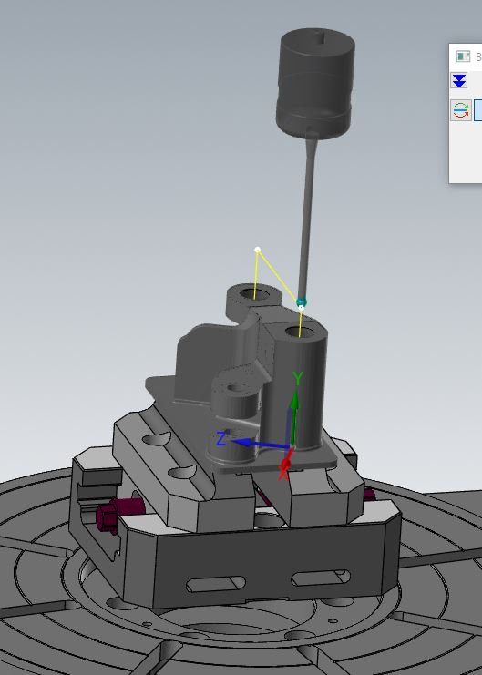
-
2 minutes ago, byte me said:
Model Prep is great, Giang the tool had a youtube video that illustrates using thr push and pull, move functions, It's crazy powerful.
Model Prep is a great tool for imported bodies. I hardly ever use it on parts created in Mastercam. It deletes mastercam's solid part history. You will no longer be able to suppress features to create geometry from the model if needed.
As for solid surfaces, it is important that the surface mesh is aligned. 90% of the time I will recreate net surfaces from solid edges. This makes morph and flowline tool paths much happier.
-
 1
1
-
-
You could use 5 axis curve toolpath, just have 4 axis output in the parameters page. We do it all the time to run chamfers along outer edge on a 4 axis mill.
-
1
-
-
I don't think your mean at all. I agree that it will be much more efficient. I wish we had been using tcp earlier. Unfortunately it wasn't available to me until now. I received the new post this afternoon from Postable.
-
1
-
-
43 minutes ago, mkd said:
<trying> getting software to correct for major machine geometry issues is not a road i'd like to go down.
high-end machines have Kinematic files that contain basic info on pivot points and whatnot. They also have comp tables to fudge the numbers like what your are seeing. These are generally not more the .001" adjustments for backlash.
You would be far better off getting the machine geometry corrected mechanically and have the tables handle the small stuff, IMHO.
Thank you. That is exactly how I feel.
-
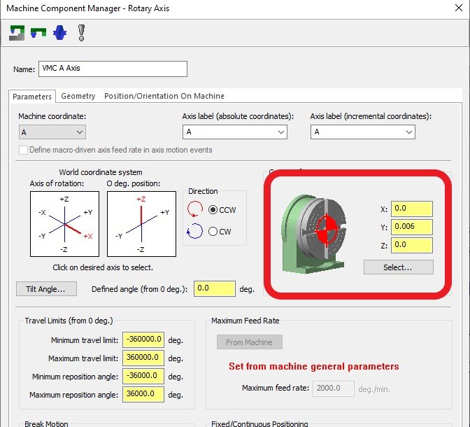
I'm looking for some opinions.
We have a Leadwell V30i 5 axis trunnion with a fanuc Oi-MF control. We do not use TCP/ DWO/ TWP everything is programmed to the center of rotation. Over the past couple of months, it had been crashed and rebuilt. The A and C axis no longer rotate together on center and the y-axis is off .010 at A90. The machine builder said that I can have the error automatically written into the post using a G68.2 tilted work plane. I've reached out to my reseller and just had a post written ($3500.00 mind you) that allows me to manually enter the shift in the machine def parameters. Everything is fine with the post for a workaround and does exactly what you would imagine - it shifts the Y whatever value I've entered. For me personally, I do not like that. I do not want my code to be altered. I want my code to be exactly what it is supposed to be. You should be able to read it and calculate everything based on the tool etc. without having to add/subtract a shift from the error of the machine. If that was the case why wouldn't I just make any rotation a different work offset and change the value there?Is it unreasonable of me to think that the error should be corrected in the parameters of the machine, similar to backlash? How do other programmers feel about this?
Thanks for reading. I look forward to some responses.
-
It's not available. You'd have to make an additional finish contour toolpath.
-
I see you already got an answer, but you could also limit the movement of the tool with "depth limits." I flowline a ton of external fillets on rod end linkage and for some reason it does the same thing moving in z minus below the edge of the fillet. I have to constantly set limits so it only travels along the surface.
-
I keep getting an alarm that started in Mastercam 2020. "MultiXPost can not interpolate between two moves with opposite orientations" If I click OK verify will close. If I click the X in the corner to close the alarm, I can run verify but I will get alarms. The alarms are at points where the tool changes 180deg. the alarm message is "Error when cutting move 4235 of op 24" (just an example)
I can verify the same file in Mcam 19 without a problem (it was created in 19 and migrated to 20). I believe it is from the way it handles the poles, but every time I change them in config they just convert back.Has anyone else experienced this and know of a solution?
Thank you!
-
On 6/17/2019 at 12:03 PM, sharles said:
I guess I don't 'need' to do it, since I also verify my parts. Normally, I just tell the simulator to ignore all similar errors for the op...but that doesn't address the fact that the simulator isn't working correctly unless I have some setting wrong...I was just trying to figure out if my relative ignorance about machine simulate was the reason for the errors and I simply didn't have some parameter correctly set...
I use both simulation and verify to check for collisions. Simulation is mostly for fixtures, and tool movement, and machine dynamics. Verify for gouges or compare to model etc. This might be obvious to some, but it took me a little while to figure it out, make sure your stock and all fixturing levels are not visible on Mastercam before you start verify. And/or turn off collision checking to workpiece. Also, make sure that all axis arrive simultaneously as shown in the screenshot above. Otherwise, it will pull the tool holder through the part on 180deg rotations.
-
2
-
-
Open the STL file associated with the rotary for that machine and translate it to the position you want.
-
16 minutes ago, gcode said:
This is most likely a post issue..
when you use a 5X toolpath, your post is outputting 5axis code, which will be point to point ( no arcs and no CDC)
when you create a toolplane to drive circle tool paths you a really creating a 3+2 toolpath and your post is outputting tilted tool plane code.
The solution is to ask your post developer to give you a misc integer switch to enable tilted tool plane output for 5x toolpaths when needed.
Thanks, I will check into that. What I'm seeing is in backplot. Same hole without rotation, just top wcs, c&t, The solid feature tool path is line segments, the wireframe is arcs. The result is the same when I post out. Line segments for the solid tool path and arcs with comp on wireframe.
-
I don't like that it won't create arcs/ or cutter comp when using axis control in either helical or circle mill when you select a solid feature. I have to manually create ops on each rotation/plane using arc geometry in order for it to use comp and arcs. The idea of simplifying the tool path is great, but the execution is not very useful.
-
1
-
-
Hey all,
It seems I have misplaced my most used function on Mastercam 2020. Does anyone else use 5 axis drill? Is there a workaround (aside from FBM)?
Thanks in advance. -
15 hours ago, C^Millman said:
Are you on the latest patch of 2018?
Yes, SP3 (build 20.0.21885.0). I believe for me, it started with sp3, I don't recall having this problem before.
-
1 minute ago, C^Millman said:
Yes this was addressed and working like you would expect.
I mean has anyone come up with a way to fix it? When I open a file that has stock models every one is turned on.
-
Has this been addressed? Anyone have a work around?
-
One thing I like to do is use viewsheets for each operation just save and bookmark it. It makes creating and changing set up sheets incredibly easy. Click on the view sheet for that op and all your set up sheet part view is ready to go. No more going through levels and turning on vises or fixtures.
-
I'm with the OP on this, verify is not right. MCam2017 with windows 7 verify was fast. 2018 with windows 10 is worse than watching the life cycle of a blade of grass. There are so many time consuming bugs it's aggravating when you are on a tight schedule. Every time I open an operation there's about a 6-7 second delay, change between parameter pages there's a delay on every one, right click for quick access tool bar another 10 seconds. Granted I know this is associated with windows 10 (because I didn't have these problems before) it's still Mastercam. Due to government security requirements we have to use windows 10.
-
2
-
 1
1
-
-
29 minutes ago, JParis said:
A real machine will proper memory isn't an option?
.gif ";)")
Hard to believe my phone has like 30 million times more memory.
5 axis curve will allow me to do what I'm looking for! Thanks! -
well that's disappointing.. lol. My intent was to rotate (transform) the tool path and post as incremental sub programs. My part has too many details and operations to post out otherwise. Any thoughts?

-
Is there a way to do this same thing when using axis substitution? It posts correctly when I turn off substitution, but post the same b value when I use substitution.
Thanks in advance. -
I'm also having a problem creating an entry point in 2d pocket. It considers the point as an open chain.
I have 2018 with the latest patch (3rd) installed. -
Yes. I'm running SP2. Which I installed by downloading from Mastercam.
Camplete Truepath G18/G19
in Industrial Forum
Posted
Good morning all.
I recently started with a new company that uses Camplete. So far its not a bad transition. However, I am having problems with a flowline toolpath that is outputting point to point rather than simple arcs. I reached out to the reseller and was told it doesn't support arcs in plane outside of G17? I'm not sure if the reseller doesn't support this or if Camplete doesn't.
Can anyone confirm this?
Thanks!