


allaces
-
Posts
25 -
Joined
-
Last visited
Content Type
Profiles
Forums
Downloads
Store
eMastercam Wiki
Blogs
Gallery
Events
Everything posted by allaces
-
Can someone tell me how to project the red wire slot shape into this housing? CUTTING SLOT.mcam
-
Than you. The reason I said scale was because the convert from inch to metric function, etc... is under scale menu. I should have said convert instead. Thanks again.
-
Can anyone tell me why I can't scale this pulley to Metric Size? When I try... I get the ERROR: Problems generating chains PULLEY.mcam
-
I can't believe how easy you made that look. I've been struggling with this since last night. I tried to redraw it many time but I was leaving out the culprit that was causing the problem. Thank you! Thank you! Thank you!
-
I tried to trim and redraw the geometry numerous times with no avail. I don't understand why it won't cut the red bore profile. Please note that the holder is purposely tilted 1 degree in this file that I'm resending. Could you please resend the file with the bore done.PLEASE FIX.mcam
-
Help! Can't revolve solid cut... Why? I get the error: Cannot determine swug geometry The red profile is what I'm trying to revolve in the solid housing. CANT REVOLVE CUT.
-
Excellent idea. I did not realize that they had that option. Thank you!
-
How do I go about tapering out the thread on a bolt as shown in the pic with red arrow?
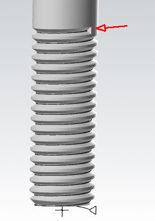
-
How can I have a progressive pullout at the end of the thread. It presently ends square instead of tapering out.
-
Thank you!
-
Can any one tell me why I can't I cut this thread on this solid model bolt? The cut command is grayed out and I can only create a solid thread profile instead of cutting it. .5 - 13 BOLT.mcam
-
Thank you for your response. I think I got what you mean... the triangle is too large and overlaps the next pitch triangle in the cut? Is that correct?
-
Can someone tell me why I can't cut a thread in this solid? THREAD INSERTS - INTERNAL AND EXTERNAL.mcam
-
I got it solved by saving it as a .step file then reloading it.
- 1 reply
-
- 1
-

-
I made a solid that seems fine in everyway, but I get this error "failure extruding sheet body" when I initially load the file in Mastercam. Does anyone know what would cause the error?

-
Thank you crazy^millman for your time and help, and Colin thank you for pointing me in the right direction. You guys are great!
-
Yes... I was afraid of the answer. I will try to make 2 parallel line paths (inner and outer segmented paths) using the ball centers that should help in determining the placement for at least the Z axis, and I will then try to fudge the angles for the other. This might get me close enough for what I need. Thanks for your help. I understand that CAM software not a CAD software but because Mastercam can do so much nowadays, I thought it was worth asking.
-
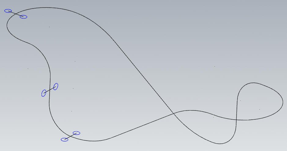
crazy^millman It seems that I may have edited my post while you were responding to my original question. I'll restate my issue in case I confused the issue: I appreciate your response, If I understand what "point segment" does is it basically divides the curves or spline into even lengths. But it does not array the (2 circle sets) along the segmented lengths. The (2 circle sets) would need to be "manually" copied and "rotated" in 2 directions to make them parallel to the segmented curves that I just created. Is that correct? If so... it would be "very tedious" for me to work out all the rotations required for 100 segments. I was hoping to find a way to avoid that.
-
I appreciate your response, If I understand what "point segment" does is it basically divides the curves into even lengths. But it does not array the (2 circle sets) along the segmented lengths. The (2 circle sets) would need to be "manually" copied and "rotated" in 2 directions to make them parallel to the segmented curves that I just created. Is that correct? If so... it would be "very tedious" for me to work out all the rotations required for 100 segments. I was hoping to find a way to avoid that.
-
Does anyone know how I can equally array a (2 circle set) along a multiple curve line as shown in the included jpg? I show 3 blue circle sets in the jpg to hopefully show what I mean. I want to array one set over a multiple curve lines equally spaced (closer than shown). I want them to straddle the curved lines and also keep them parallel to the curves.
-
flatsurf.dll problem. Please help!
allaces replied to allaces's topic in Mastercam C-Hook, NET-Hook and VBScript Development
John, I'm using X3 and the file you sent was probably from a newer version so the file won't load for me. Could you save it as X3 and resend? Thanks again, Ray -
flatsurf.dll problem. Please help!
allaces replied to allaces's topic in Mastercam C-Hook, NET-Hook and VBScript Development
John, Thanks very much for your reply. Can you tell me why flatsurf.dll won't work on these parts? I'm not clear on your explanation... Can you flatten all the parts in the file for me with text notes explaining step by step your simple way of going about it? I’m not sure how to work out the angled radiuses of the corners. If so... could you zip and email it to me the flattened file at [email protected] Thanks again for your response and your help... Ray -
Hello, When I flatten the 3d parts with the flatsurf.dll c-hook, the resulting 2d contour lengths do not match the original 3d contour lengths. Can someone tell me what I'm doing wrong or is there a problem with the C-hook? If the c-hook is the problem... then can it be fixed? If not... then can someone correctly flatten the parts I've included by other means. These are straightforward 3D shaped sheet metal parts that should not result in stretching and/or ripping. The "3D PARTS TO FLATTEN.MCX" file I need flattened can be found at: http://Allaces.com/PARTS/ Any help with this problem would be extremely appreciated... I'm hoping that I won't be forced to purchase and learn a new expensive program just to be able to do this function. Thanks, Ray
-
My problem was with my graphics card driver. I uploaded a new driver as was sugested by a respondent and voila! It now works as it should. Thanks again! Ray ==================================== How do I set Mastercam to be able to completely view a large file that's over 3 1/2MB? This file won't completely come up on the screen when "all levels" are turned on. There is a lot of surfacing in this drawing. I have to disable a few levels (surfacing) or the program will bomb (apparently over some kind of file size limit) I tried uping the values in the "screen", "configuration" menu but it does not seem to help. Is there another menu area for setting up larger file limits? Thanks to anyone responding. Ray [ 03-31-2002, 04:23 AM: Message edited by: allaces ]
-
Help? How do I set Mastercam to be able to completely view a large file that's over 3 1/2MB? This file won't completely come up on the screen when "all levels" are turned on. There is a lot of surfacing in this drawing. I have to disable a few levels (surfacing) or the program will bomb (apparently over some kind of file size limit) I tried uping the values in the "screen", "configuration" menu but it does not seem to help. Is there another menu area for setting up larger file limits? Thanks to anyone responding. Ray