


Bill Craven
-
Posts
279 -
Joined
-
Last visited
-
Days Won
14
Content Type
Profiles
Forums
Downloads
Store
eMastercam Wiki
Blogs
Gallery
Events
Posts posted by Bill Craven
-
-
Hey Alex,
Is the MachSim included with an IKE post?
-
For what it is worth:
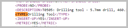
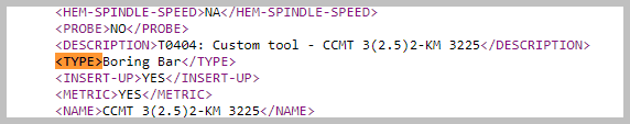
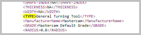
The XML file that Active reports generates does have the Tool Type field available as: <TYPE>
-
 1
1
-
-
One of the thiings that I implemented at a shop many, mnay years ago was: The Accounting department couldn't close a job until the programmer brought them the finish Mastercam files (Z2G so they had the post that they used), setup documentation, and the finish programs downloaded from the machine. Then those filles were saved to a secure server with prints, run times, etc.
Too many times we had repeat jobs and the original programmers couldn't find the original programs (that they were storing on floppies in their toolboxes) and we had to go back to square one. Or if they did find the Mastercam file, it was not the latest one and the NC files had been modified extensivley at the machine becasue their posts were not error free.
At another shop, I implemented saving Mastercam feature operations as seperate Mastercam files that were used as example files that had worked well and saved to a special library on the server. Similar to maintaining operation libraries. But this was easier for the programmers to review and then incorporate into their new programs.
One shop I went into had a sign in the office as a joke: "We are too busy to get organized" But it was true for them and they suffered for it.
-
 4
4
-
-
Excel table of contents example bc2.xlsm
I have attached a spreadsheet that I use for keeping track of my projects. One of the unique features of this spreadsheet is that it has a self healing Table of Contents.
What I mean by that is: you can add new sheets, reorganize sheets, delete sheets and when you go to the Table of Contents page, it will rebuild the table of contents.
I have a few bogus sheets in there as examples. the last sheet is instructions/hints on how to use this sheet.
One of the pages that I have in there is a group of tools with some basic parameters that I will save as I am selecting tools so that when I am entering information about a tool, I don't have to go back to the tool manufacturer's page.
I will add in blueprints and machine information. Most of the things that I need end up in one document for that project.
Something like this could become "The Book" for a part with all of the setup information in it.
-
3
-
1
-
-
39 minutes ago, Newbeeee™ said:
For auld time sake, IMHO the most important thing for a 'grammer to do, is convey the minimum required information to the shop floor, to swiftly and successfully make the part. Obviously, both concise and accurate information. The reason why I say minimum, is because some of these set-sheets are data creators - and IME, people's eyes glaze over - they don't bother to read it. Less is best.
And it really should be (as close as possible) one-click.
I totally agree with this. I hate to say it but there are a lot of people out there that don't take the time to CAREFULLY read setup sheets or their reading comprehension skills are very poor.
-
3
-
-
1 hour ago, Newbeeee™ said:
"implementing new" can be a "bit of a PITA"....(as AR, initial View Sheets, and Tool manager as a few examples, show)....
Learning curves can eat up a lot of profit... What is the "Tool Manager"?

-
49 minutes ago, So not a Guru said:
but a squirrel distracted me
LOL. "what's in that hole? Is it a rabbit tail? I better go and investigate"
I played a tiny bit with the new IKE post, but that same squirrel...
-
 2
2
-
-
Newbeeee,
I think that one of the things that really hurts Active reports is how difficult it is to learn to modify the templates to get the output that you want. We are supposed to be programming parts. ("Why isn't that spindle running?")
Sometimes, I would spend as much time documenting a project as programming. The information was there, we just had to get it out of the Mastercam file.
I remember when Dave Thompson was with IHS, he was my mentor for Post Processor generated setup sheets. Way before AR.
I spent my own time learning AR. I primarliy do turnkey projects now and wanted to have some polished looking results that I could generate with one click of the mouse. I have gotten close to what I want, but 2023 broke it for me.
Jim Varco's product is very good and it is pretty easy to make many modifications.
Gunther's X+ is excellent and I use it for quick double checks of settings. (Did I remember to turn the coolant on for all operations?) 15 seconds later, I have my answer. I am sure I could do more with it, but I have invested time and energy in AR.
There have been whispered rumors swirling around in the mist for years that CNC was going to implement a new Setup sheet report writer.
-
1
-
-
I am in the middle of a large critical project and don't have much time now, but will help if I can.
A couple of things about Active reports:
One of the biggest problems (in my opinion) is the lack of fields available to store information in. I have to get very creative on finding places to store information and part numbers.
Not all information is available for extraction from the Mastercam file to Active Reports. The Mastercam file is realy a database of information about the tools, about the operations and all of the settings... Those features are extracted by the RPX parser for a report, but not all of the fields are availble for extraction. Whenever CNC adds new features to Mastercam, it may take a couple of generations/Versions of Mastercam before the information is available for extraction for Active Reports.
Sometimes when CNC changes the internal structure of the Mastercam file, they "break" my workarounds and my sheets no longer generate correctly.
I have tried using Acrobat Pro to convert a saved PDF setup to Word and it mostly looks okay, but when you start editing the doc, it goes wonky pretty quick.
I typically use Snagit for capturing screen images. It makes them very easy to paste into a Doc or Spreadsheet.
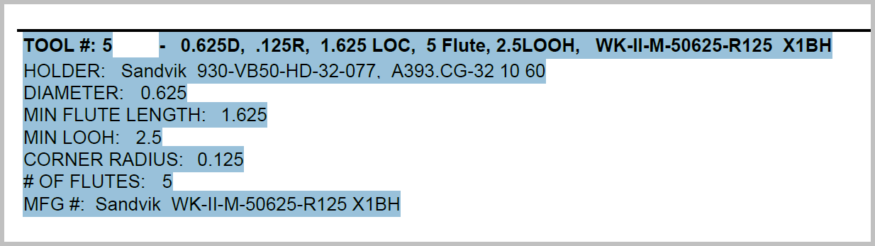
I have created a few Active reports that don't have a lot of borders or other features and use that as a Word "transfer" doc. After saving as a PDF, I can grab a group of text items and copy them and then paste them directly into Word or Powerpoint.

All of the text highlighted in blue from this PDF can be copied and pasted directly into Word or PowerPoint.
-
1
-
-
Another possibility, although I haven't tried it, might be to create a manual operation as a comment and include that in your setup sheet. There is a 750 character max limit to the size of the manual entry but you could do multiple manual entries.
With Ron's PDF editor suggestion, you could add photos and pages of text and control the font etc. AND you wouldn't have to open Mastercam back up to enter setup information and notes which might be gathered after the proveout is done.
-
Ruth Delisle is the main contact at CNC software for Active Reports.
If you send an email with your questions to [email protected], it will most likely end up in her inbox.
-
1
-
-
4 hours ago, ___ said:
There is a multi-threading enabled option in the config, on the off chance that it's disabled..
The Multi-threading option in config is enabled. Thanks for the suggestion.
1 hour ago, cncappsjames said:I use the method Ron Branch showed me.
Make a stock model of the selected paths and let it generate. Tighterntolerances are better. Activate a new empty level and set as main level. In the ops manager right click on your stock model and create a mesh. It will save that mesh to your main level. Go into the stock model op for stock, select the new mesh. Deselect all the toolpaths associated to it. Regen.
Create the next stock op, the previous mesh will be your current stock model, select toolpaths to machine that stock model. Let it generate.
Rinse. Repeat as often as necessary.
Thanks for the response James.
The wash rinse and repeat is my normal way of creating StockModels. Including the CTRL mouseclick to deselect the operations so that it is not regenerationg the toolpath, just using the Pmesh.
But after i get a large number of stockmodels, it takes longer and longer to generate a new stockmodel.
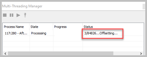
Watching the status of the multi-threading dialog box is painful. The offseting slices update so slowly.
I am using a lot of Dynamic toolpaths with small stepover and I expect that those toolpaths will take longer to generate, but I really can't afford to wait an hour or more for a single stockmodel.
Sorry for the rant, I am frustrated.
Before anybody asks, I can't share the file it is an ITAR part.
-
1
-
-
Is there a limitation to the number of Stockmodels that Mastercam can handle before the generation and regeneration of the stock models slows down to make it unusable?
I am currently stuck in 2021 because of a customer.
The first few Stock models generate fairly quickly. Then they start to slow down, even to the point where I have to just turn delete tham because they are taking an hour or more to generate.
What are solutions that you have come up with to stay efficient?
I am not curretnly using them for stock for subsequent operations just visual verification that I havn't missed anything.
I have also noticed over the years that Stockmodels don't always start regenerating right away. I have a desktop gadget on one of my monitors that shows what the cores of the CPU are doing and a lot of time when I create a stock model, it just sits there with nothing happening. Then after several minutes or more, it will start crunching and the cores will light up.

Edit: My primary use of Stockmodels is to be able to run verify from an intermediate point of the program rather than starting from the beginning each time with hundreds of operations.
-
1
-
-
This is interesting Pete,
Thanks for the insight. There is so much stuff going on behind the scenes that the average person is unaware of.
"Well, why don't they just..." It's not that simple.
-
1
-
-
I just tried this and all that showed up was the outline. But as I moved the mouse around the interior of the outline, I could see that other entities were in there.
I slelected everything and changed the color to green and everything was there.
I have a black background and the PDF geometry came in as color255 (black)
No warning about the geometry being the same color as the background color
-
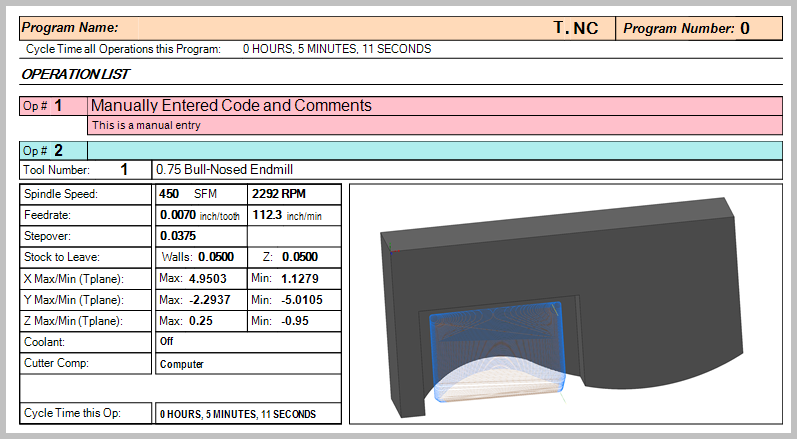
If you create a manual entry as your first operation, If you run the MT setup sheet, the manual entry operations are posted to the Active Report. (they may post out in Mill or Lathe also)
I use the MT setup sheet for everything. It will post out Mill operations, Lathe operations, and Manual entries. I have it color coded so that the different types of operations show up in different colors.
-
2
-
-
4 hours ago, gcode said:
For mission critical tool lists with Capto stacks I make a SolidWorks assembly of each tool and use that to create a tool sketch
It's a ton of work.
Yes, I believe that is the very definition of a ton of work. And then even more work to bring them into Vericut...
Okay, So I ran some more tests with the high-feed tool definition and didn't have any cusps. (I may be on the 'Cusp of success' with this. Now is the time for a collective groan)
My tool build strategy going forward will be to use the tool and inserts STEP model define the tool and give it the proper names. Then build a solid model for the holder and adapters and name the holder with the proper names.
That looks like it will work well. I'd post a picture, but I don't have any kbs left for embedding
-
1
-
-
2 hours ago, gcode said:
I was asking if the latest version of the high feed tool was generating a good toolpath in Mastercam,
or are you still running the bull endmill definition?
Sorry, I misunderstood.
I am running it as a high feed, but haven't actually cut anything yet.
When I have time, I still need to run some more tests to verify that my issues with cusps are better.
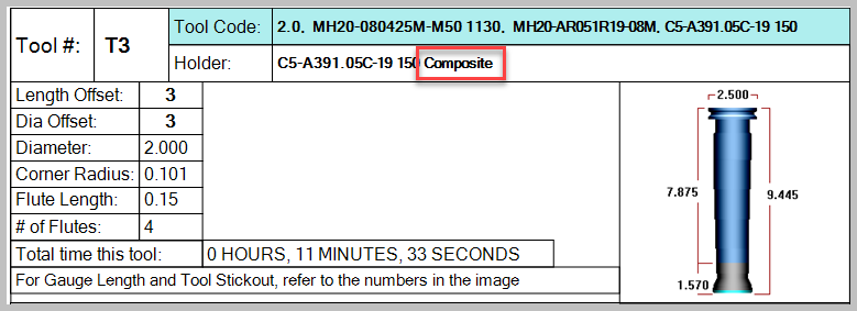
I am also trying to use the create tool assembly (which I have not used before) so that I can more easily keep the tool separate instead of building a STEP file with the cutter and extensions and adapters. I like the tool assembly concept but it causes problems with my Active Reports setup sheets because it lists the holder as the adapter that is just above the tool and then says "Composite" I want my setup sheet tool list to have all of the parts of the tools listed so that the setup person will have all of the tool part numbers for setup.
-
2 hours ago, gcode said:
Is this tool giving you good results?
Yes, It has amazed me. In theory, I am removing around 12 cubic inches per minute (Because it is an Optirough dynamic path, I am probably only getting 50-60% of that due to slices in corners etc. Still very respectable.)
2.0 diameter cutter. Material=4140 steel. SFM=625, ftp=.031, feedrate=196 ipm, depth of cut=.045, stepover=1.3, hp=11, no coolant. Some vertical walls.
After 27 minutes I couldn't tell which edge had been used. The only way I could tell was that there was a little discoloration on the chip-breaker. I expect that I should be able to go for an hour before indexing the inserts.
-
First off, I want to say how much I appreciate this forum. Thank you all very much.
I tried several different things and will list them below.
I changed the shank diameter to 1.7 from 1.997 and the toolpath regenerated the way that I wanted it to. this is the quickest solution, but not necessarily the best.
I built the tool definition just using the tool and inserts and then brought in the holder from a STEP file of the holder and extension. I can see where this will probably give better collision detection. but now my tool holder library just became pretty much obsolete and assembling holders and extensions will be more time consuming and difficult keeping track of all of the variations. I was concerned that my setup sheets might not show the correct gauge length, but that worked fine.
I am aware of the incorrect STEP models. You get better results if you save the detailed models. For the detailed model, I ended up with a 1.997 diameter cutter. Better but not perfect. I don't know what their tolerance is for that cutter
I also built up a tool definition based upon a wireframe. The advantage to doing that is that I can simulate the undercut on the face. I always generate a wireframe tool when doing turn milling. I always make sure to break the link to the level that the geometry is on so that I can save that tool to a library and use it in other programs. I used the holder extension combo for the holder

-
2
-
-
-
Okay, I tried that. I made it .25 Not much change. Then I made it .45 for the LOC. That made it better but it is still way off what
The cutter path is now not even close to model.
It should look like this:
-
Ah...
Thanks Tom, I will give that a try.
-
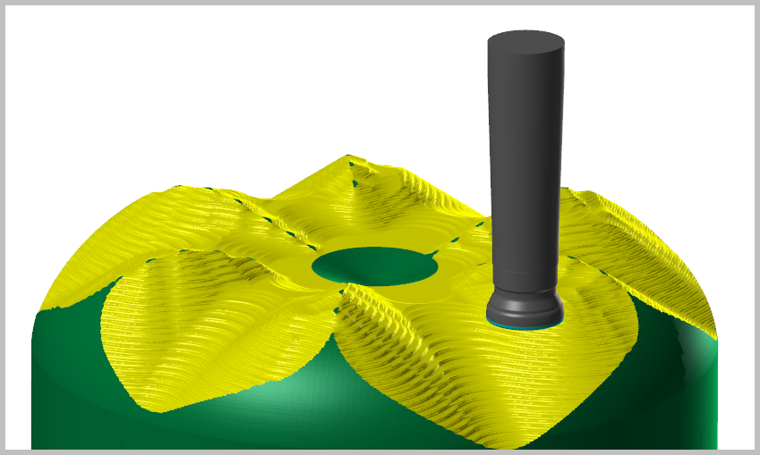
I ran into a most unexpected result today when using a tool defined as a high feed mill.
I am using Mcam 2022 for this part.
Sorry, I can't share this file.
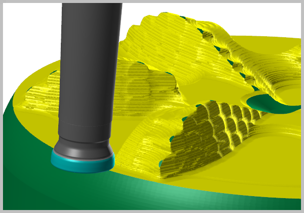
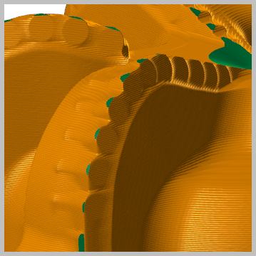
After defining the tool in the thread above, I used it in a very large part and this is the optirough toolpath that was generated:
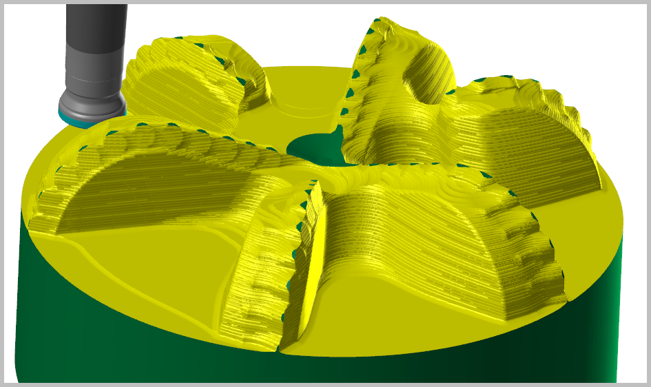
I changed the cutter to a bull nose with embedded geometry from the manufacturer's STEP file and then made NO other changes and regenerated the operation and this is what I got and what I was expecting:
I went back and double checked everything and there is definatly something going on with Mastercam using some of the information from the high feed definition to keep it from stepping down a vertical wall and ruining the outside edge of the insert.
BUT it is not consistent. I generated some other toolpaths with the high feed cutter definition and it worked as I expected.
The cutter is a Sandvik 2.0 dia. MH20 cutter which they are calling a "High-feed pocketing" cutter and it works well for that application. I ran a test in 4140 at Vc=625, Fz=.031, Ae=1.3, and Ap=.045. after 27 minutes in cut, I couldn't see any wear on the insert and the outside corner wasn't blown out.
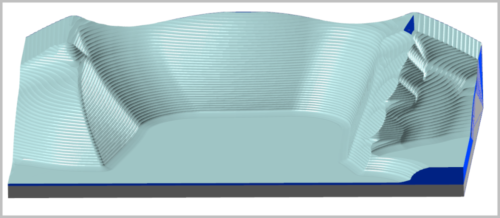
After 27 minutes:

So: I am back to defining high-feed cutters and bull nose and will deal with the cusp problem because I need to be able to step down veritcal walls.
I am going to reach out to Mastercam and see if they can offer some insight to when this happens and if there is a way to turn it off.

IKE post question
in Industrial Forum
Posted
Thanks Alex, I was confused by the verbiage. It sounded to me like Machsim was included, but now I understand that what you are saying is that the IKE post has all of the logic integrated into the post to drive and control Machsim.
Thanks for the clarification.