


JayM
-
Posts
180 -
Joined
-
Last visited
Content Type
Profiles
Forums
Downloads
Store
eMastercam Wiki
Blogs
Gallery
Events
Posts posted by JayM
-
-
Got it. It's in the View tab.
Crazy place to put it

-
The spindle speed will be set to max RPM but it will not adjust the feed rate.
-
Exactly. The material calculations for tools work well for some people, generally those doing very basic machining or operations.
Good luck.
-
Thanks G! I now have the levels and planes separate from the op mgr.
The panels can also be "torn" off and stacked on top of each one. I like to stack the Levels manager and Planes manager on top of one another.
-
I'd say it's easily in the top 10 (maybe even top 5) "Most Asked Question" here at the forum. I know I too asked it some 14 years ago.

I remember the same thing, probably about 12 years ago.
-
"Better" is a difficult thing to answer. I generally recommend creating a tool library per material rather than driving by the material. Reason being it is possible to get much more specific about the speeds and feeds for your tools if they are defined in the tool library. Driving a tool by material will give general speeds and feeds for each tool. For example, a given 1/2" carbide endmill. The speeds and feeds can easily be calculated based on the number of flutes and desired SFM and feed/tooth, but it does not take into account the cutting length. If you have a short cutting length, 1/2" that could be driven much harder than a long cutter length 2".
-
I have....it is different, but a good move.
-
If you have a Nethasp then you can certainly access the license over a VPN.
First make sure that the Nethasp license server is installed and actively serving the license to your local network. If you are using the Nethasp connected to you current computer then you may need to install the Nethasp license manager.
Second, setup a VPN on your network. You may be able to do this through the router or through your server. If you have an IT department/company contact them, they will know exactly what you need.
From your remote location (house, hotel room, coffee shop) you will connect to the VPN through that locations internet service. Once you are connected, it is like your computer is actually in the office and Mastercam should be able to find the license.
One more thing, if Mastercam does not locate the license, modify the nethasp.ini in c:\program files\mcamx9\, and specify the server IP address.
There are many customers who access Mastercam licenses via VPN but if it doesn't work for your company your reseller will not be able to help.
-
It happens for a variety of reasons, the specifics are not important. It is a very simple procedure to correct, use JParis's steps and move on...
select all ops >> right click edit selected operations >> Change nc file name
set your name, green check and post
-
Hi
May be you need export the piece in SW in STEP or IGES, I have SW2016 and MCX9, always I export the pieces like this way.
The reason is the date of the update of this softwares, for example, MCX9 was presented on July 2015 and SW2016 on November 2015.
There is no issues importing SWX 2016 files into Mastercam, if you have the update that JParis recommends. Also I would never recommend using an IGES file if anything else is available. IGES will give you a surface body instead of a solid.
Go to Mastercam's download page
-
Is there a way to add MFGs to the list of names in the tool manager?
The list is called "Manufacturer Name", it is a drop down in the general Properties menu.

Was told this is being added in next version....just have to wait till......then
-
Simple,
solid chaining, don't do it
It is extremely limited except for the most simple geometry. You will have FAR greater flexibility with wireframe
Moving to the Main forum, the educational forum is for students and teachers
Except for many dynamic toolpaths. Choosing solid faces for machining and avoidance regions is usually pretty easy and efficient, depending on the model of course. Edge chaining still leaves some to be desired.
-
Finish Contour will jump on the first couple of passes, especially with a very small step over. You can eliminate some of these by setting Advanced Settings > Only between surfaces. Also change your ramp length to a much smaller value, between .1 and .01.
For rouging the part you might try a large tool that can overlap all of the material left, and just use the same toolpath for roughing as finishing, just leave stock on the roughing one. If you can upgrade to X9 I would recommend using Optirough with a Stock Model.
-
very nice. ive never gotten it that good using a surface toolpath.
but it does still have a zipper line.
threadmill will eliminate that.
Yes a very clean way of getting short code from the program. I have been trying to get the surface toolpath to output the same way, it just doesn't want to see the surface as a series of helix's.

Another option would be to use Surface Finish Contour with the Ramp option turned on. A short ramp between passes will usually eliminate the "zipper" line, depending on setup.
-
Change your cutting method from "Spiral" to "One Way".
It is a balance of what is important. "Spiral" will give a toolpath with zero retracts but essential runs point to point, "One Way" will filter to a very short program but steps down between passes.
-
Try replacing the post in my file with your machine definition. It could be something in your post. If my program still comes out shorter their must be something different in our toolpaths. Upload your file again and I will take a look.
-
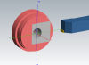
Here is an example with one arc move per step down. About 500 lines using Mill default
-
The Issue I am having with the Flowline is that it gives nice smooth toolpath, but its all tiny line segments. But one I turn up the tolerance larger than about .005 it starts adding a bunch of rapid retracts.
Turn on tolerancing to get G2/G3 arcs
-
 1
1
-
-
Not much point in drawing the actual high feed profile. You just need to define it as a corner radius endmill. Usually the Manufacturer can give you the theoretical CR.
I agree. If it is a high speed face mill, the manufacturer probably has specified the "correct" radius to define it as. I would not recommend trying to finish profile with the tool, they are not precisely repeatable and that would be the only reason to get the exact profile.
-
Some more information would be helpful to answer your question. What tool do you use for finishing? What surface finish do you need?
Flowline is good for this part, or contour. Both will give you similar motion. You could also use the High speed spiral toolpath that should work well for this part. I don't see any need to use the scallop toolpath. It is a very simple shape so good choices are pretty open. If there is a specific issue that you are having with flowline describe it so that we can address that.
-
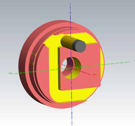
I am not sure that this is a bug. See the screen shots below, this is what I get whenever I verify your part from X9. It may be a setting in your program, in the Simulator Options, do you have 5-axis set?

-
Would I run on left or right cutter comp vs Center or off?Surface toolpaths do not use compensation (G41/G42). All motion is calculated from tool centerline, Mastercam will offset the XY position based on the tool diameter and tool nose radius.
I was using the .125" tool because I have a feature that needs it, but it amounts to about 5% of the overall surface operation. I may split that off into its own little surface, and then use the .125" tool there. I need a .065" internal radius and that's why I'm using that tool. I had it finishing the whole op though, and that was taking forty forevers with a .002" stepover.
I may go back with the same .25" ball tool that I did the roughing with, and try to make a finish pass with it on the 95% of the surface that remains.
If you find yourself programming these features often I would look into upgrading to Mill 3D. The restmilling operations will save you a lot of time programming and machining.
-
1
-
-
tried to download the linking prog from Mastercam. wont run on my computer, missing dll i think or computer restrictions. is there anyway to get the older maintenance release files. looking for X4 files.
Thanks
Contact your reseller, they can help you get the install files.
-
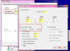
Thanks Ron, I can see where that would be very useful, but why would this operation just assume itself to be G55 when the grayed out value in the operations work offset was "0"? I didn't have to change that value in the field to get the correct output, I just had to check the box.
I only see "Renumber work offsets...", I don't want to renumber them, I want them to all be set to my choice.
My reseller also thought this behavior was screwy, not saying that as a rebuttal, just to let you know I'm not alone in being perplexed by this.
Which Mastercam version are you using? This behavior was changed I believe in X8 or X9. If you have X9 and set the Work Offset # in the Plane Manager all toolpaths that are not explicitly set (have their boxes greyed out) should reflect that setting.


Variables? Macros?
in Post Processor Development Forum
Posted
It is possible to have Mastercam post output macro variable codes like T#1 T#2 T#3, very easy actually. But this could cause some issues depending on how your program runs. For example what if you have more than 21 tools in a program? What if you use the same tool twice in different locations?