honeybunches
-
Posts
174 -
Joined
-
Last visited
Content Type
Profiles
Forums
Downloads
Store
eMastercam Wiki
Blogs
Gallery
Events
Everything posted by honeybunches
-
Looking at an older machine for some aluminum work we need to do. has a Fanuc 16 on it. Rated max feed rate (for what thats worth) on the machine is 600ipm. I would be just fine with that if the machine could actually drive a decent path at that speed. Can anyone elaborate with the certain control series and available options so I can at least have an idea of the real ability of the control? I know Fanuc is about the worst at charging for every little detail so any other owner may be left in the dark with just what the control was setup to do. Now I realize machine mechanics would play into this as well, but trying to get an idea from the control side. Many controls today, we can actually look up the block speed processing rate and blocks of look ahead and typically have a good idea how fast the control can go. Seems I was always in the dark with fanuc
-
We have our reseller scrambling around to find a post, and looks like this will not be happening so I wanted to find out from anyone here familiar with Hitachis, are they different enough that we cannot try to mod a different post? The machine has a Seicos Liii, and has C, Y, live tool, sub, sub ejector, parts catcher. I know this is an OLD bird and I have heard horror stories of guys having to splice code from a mill post just to do milling operations! I am sure we have a basic Seicos lathe post but that would leave LOTS of things out in that sub. You have spindle sync, orient on the sub, ejector, etc. that need to be covered. Do we need to just start looking at 3rd parties for posts? Or any idea which direction would look better if we modded our own? Have done this before but I am not a pro at it. If I am somehow stepping on toes for asking , please disregard.
-
converting from Haas to Okuma control. Program differences?
honeybunches replied to honeybunches's topic in Industrial Forum
Another guy has already checked and we already have an Okuma post that works just perfect. I just got so used to subroutines and such that I would like to have the option. If I need to change a drill depth, I change it in one spot. -
converting from Haas to Okuma control. Program differences?
honeybunches replied to honeybunches's topic in Industrial Forum
Thanks. I have been looking at this and would like to get some general ideas which way might be easiest to fix this issue. I am not all that concerned about directly converting any Haas programs, and I would just repost. However, regarding the post, I am not yet sure if it would be easier to edit my existing post for the Okuma or maybe edit a generic Okuma post and work it up? Here are the things I have modded in the fanuc post. 1. Work offsets with subroutines. I define a variable in MCX as the amount of offsets I want to repeat the work. The program then generates with internal subroutines, repeated as many times as I indicated in the variable table. Example, I want to repeat the same work at 4 offsets, I enter variable = 4, I will get subs of G54,55,56,57. If the variable stays as 1, no subroutine would be generated. I simply LOVE subroutines!!! Typically if something needs changed, it would be on all parts. Obviously there are drawbacks to. 2. The work offsets, count up, then down, then up, etc. So on T1, it would run G54,55,56,57, then change tool, and run G57,56,55,54. Now some of this was done to optimize for older machines with slower rapids and apparently machines don't want to reposition the table while doing a tool change. This became more of an issue on a longer travel VMC. LOTS of waiting. Other simple adjustments were to move the coolant turn on to ensure it was flowing before making chips. I also added a work coordinate at the end of every program, usually G110, X0, Y0. I would then simply jog the machine to where the best place is to change out work depending on parts, and set the offset there. Can I can some ideas which will be an easier way to go here? -
I finally have a post working just as I like it but it is for a Haas. I was looking to run programs on an Okuma OSP control and curious if these will be small changes if any, or a complete start over? These are both VMCs. the Haas's are carousel changers and Okuma is side mount but I want to say I simply disabled the tool prestaging in the post.
-
Debate on MCX avoiding fixtures based on settings or colors?
honeybunches replied to honeybunches's topic in Industrial Forum
Yeah, I think I hard coded a mill post to lift the Z when moving to another offset. I decided it was a small price (in time) to pay for a little safety. But I thought there was a way to set a fixture "color" and MCX will see that as a "do not hit that" kinda deal? Sounds like not? I guess I find some folks post out and "let'r fly". I like to put in some M01s and sometimes with block deletes so I can monitor things closer on a first run. -
Got in a debate with a guy that programs with MCX and I could have sworn there was a simple way to simply tell MCX "this is a fixture, don't hit it". Now, this might just be my bad memory when playing with custom lathe tool holders and he only plays with mills. He was mentioning tricky rotations with 4 axis HMCs to not hit tombstones, vises, etc. Previously they would retract the Z way back. What are the options there? I think they have X5 or X7 now. This is purely just an inquiry, I don't have any specific issue at the moment.
-
Thoughts on slotting operation in steel
honeybunches replied to honeybunches's topic in Industrial Forum
Just talked to the guy and after nearing what this was, a full radius is much more structurally sound and this is an engineered product with certs and proof test. So basically we have a 9/16" wide slot, 3.25" long, in 2" A36 bar..... Only real decision is do I just ramp into this or drill. The way I look at it, the round surface would need center drilled so 2 ops. I am leaning towards 1 tool..... Issue I have is we don't have anything bigger than 3/8" cutters for steels. Only the 3FL Aluminum cutters and I won't even try that. We have Imco powerfeeds for steels and know they run nice but don't have near enough stick out for that. Would have to flip. Hmmm. Time to go dig around in the bin I guess.... -
Don't do many odd jobs but trying to help a guy. He needs some 9/16" wide thru slots cut in some 2" round bars. Because this is a small one time job, I was going to reach for a smaller cutter and such but I still need to reach 2". I would also like to minimize the corner rad so a smaller tool is preferred. Thoughts on the tool selection and path for this? I would rather not flip the part over but if I do, I am trying to think of an easy way to index the bar for this. Obviously using a 4th would be best but don't have one with a chuck. Just wanna throw in a vise and get it done.
-
Trying to help someone out real quick and figures things would not go as planned. The area in teal needs machined. The radius of that dished area is .130 and I would like to just use a 1/4" ballnose for this and make a couple rounds. I cannot find any surface path that will give me what I need. Ideally I would like to start at the outside and gently ramp or helix in and walk around the bottom towards. That little notch is no issue and will be deleted from the design so I am hoping and I can just drive past it like it was not there? Contour pic mod1.pdf
-
I was able to get the custom tool modded and working but anytime you move the insert, you have to realign with the origin and that has become some issue here. Seems I was able to select a point on the tool tip that got it driving right in X but Z was .005 off. I have fudged it for now by leaving.005 to my Z stock but I would sure like to know what I missed there.
-
I have saved a close tool to the library. It is a .500" bar with the DCMT insert but the main issue is the orientation of the insert is wrong. Is there not an easy way to get MCX to change the presentation of the insert? Is there an easy work around here? Also, since I have never done this, once I save the modded tool to a level, how do you use the modified tool?
-
I am trying to use a tool that I cannot find in any library. It is an SDJCR bar, .500" diam, and runs a DCMT insert with only a 3* lead angle. Do I have to go through the task of creating a model for this tool or is there some simple way to modify an existing tool?
-
Lathe tool will only follow one side of chain.
honeybunches replied to honeybunches's topic in Industrial Forum
^^^ Your a GD genius! That was easy! Thank you! -
Hoping I just have another simple setting issue here but I am cutting a sort of V shape out of round stock with a VNMG insert. You can clearly see the insert and holder have clearance and I have even added extra lines to ensure I don't have something wrong with the geometry. Basically the contour chains correctly along the path I intend but when the tool path is created, it refuses to cut on the turret side of the insert. If I select on the lines on the spindle side so the insert is not cutting on the back side, it will cut correctly. Is there a setting to allow the tool to follow such a contour? Imagine simple lines such as \ and /. The / part will not cut, but if I only select the \ part, it will follow.
-
Best ways to orient and create lathe profile for part
honeybunches replied to honeybunches's topic in Industrial Forum
^^ Yep! Thanks. I figured it out about the time you posted. I don't have to rotate parts much I guess. That got me all fixed up for now. -
I guess we have not programmed our lathe in a long time! Typically just hand program most basic things. I am not sure if we setup a post for our lathe or just used the generics in X5 but I am trying to use the generic slant bed 2 axis. When I bring the part in, the WCS views for "top" are wrong so I select "right side" and get the part flipped how I need it and axis looks right. I then create/turn profile. That profile is on the wrong axis and seems to try and follow the Y and I need it to probably follow the X. I am not sure if the default machine definitions are causing this or I simply need to rotate something? I remember in years past having to use Xform rotate to get the part looking correct but when I do that, it simply rotates about the Z and there is no option to rotate about another axis. What am I missing here? When the part comes in, my axis are correct and part is looking up but of course I need the part on its side for programming our 2 axis slant lathe.
-
Not interested in arguing but I think what you mean is "pull the spindle down" as the helix of the cutter would pull the cutter into the material. This would be evidenced by pulling parts out of a vise. I have never heard of them being pushed into the vise. I agree with what you are saying though. However, I think we have pretty much confirmed we don't have a bearing issue. Talked to 3 pros now and with good noises, no heat, no odd runout that is not consistent, no axial o radial play, we are chasing runout. I am testing now but strongly believing this is being caused by the drawbar. I think the balls or the collet nose has an issue.
-
I appreciate the responses. We know we have runout that exceeds what is normal so I think getting that fixed would be best before we start trying to grind tools to fix it. I know on other machined, we get the typical swirls but nothing you could hang a nail on. What we are trying to determine now is the taper or maybe even an odd drawbar pulling issue because the holder is getting very good contact and pros indicate if there is a small low, the rest of the taper should be correcting that and running the tool true. Indication is bell mouth usually starts showing up and cause for grinding but we actually get good contact at the bottom. I am puzzled at the moment and hoping we have something like draw bar fingers causing this.
-
What does the "more material" part do? Is there indication of what would be worn that causes this? I am doing some machine testing now and it sure looks like the spindle taper may be the issue as there is a low spot and that is consistent with the runout at the tool. We marked with a sharpie and then ran the tool.
-
Yes, we have looked back through several parts we make and all get a similar floor finish. Plastic or Aluminum. I am talking with some spindle guys now to try and chase down the issue.
-
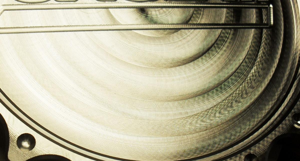
This finish is a .010 axial DOC, 60% step over, 7500rpm, 60ipm, 3fl cutter no radius. I already plan to throw a radius cutter in but I also know it won't totally fix the issue. There is something more going on. We had an old CNC knee mill that would do a better finish than this! That other outer band to can barely see that is higher was the same but .005" DOC and 80ipm. Pretty much no difference.
-
I know my issues are machine specific and this may not be the best place to discuss but I am fighting swirls you can hang your fingernail on the floor finish of 6061. No amount of feed/speed, tool path, etc will change that. I have reviewed several parts from this machine and it just plain sucks and caused excessive debur times. I know we have some runout in the spindle due to the taper having a low spot so we test every single tool and make adjustments. The tool we are using now is a 3/8" square end with .0008" runout. I have read that the head tram may be causing this and one that I sort of forgot about. I also was thinking about spindle bearings but this spindle sounds just like new, no heat, no finish issue on the walls, and no dimensional issues that would point me to bearings. That is an expensive "guess". For my tested floor finish, I am running a finish pass of .010" and another at .005". There is no difference at all. Really no difference between the rough and finish passes either. Any thoughts on the runout being the cause or tram?

-
Got it, thanks! just needed to toggle the "change tool/color". Working great now.
-
Guess I have never really had to do this. Looked in the books but this might be easier. I just need to assign different cut stock color to different tools. I can see in the verify settings different tool numbers and color assignments but I am getting only a color for uncut and cut stock.