


ARP
-
Posts
60 -
Joined
-
Last visited
ARP's Achievements
")
Newbie (1/14)
0
Reputation
-
Mazak alarm 398 conveyor overload off
ARP replied to Smassey's topic in Machining, Tools, Cutting & Probing
I see this is a bit old, but we had the same issue and it turned out to be a bad relay. It kept tripping and the conveyor would shut off. Mazak finally came and replaced it. Good ever since and that's a few years ago. -
Thanks for the help jlw! I had a look at your work and almost got time to work on it... then got de-railed on a bunch of other stuff. I'm going to work on it this weekend when things are quiet at work. Cheers,
-
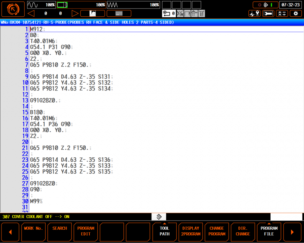
I'm a long time VMC and Mastercam user. I am now working for a place that bought an HMC and has no Mastercam. I'm using a Mazak HCN-4000 horizontal and Mazatrol to machine castings in low volumes. The machine has a Renishaw OMP-60 and software. The castings vary enough that I have been probing every one before machining to ensure my work offsets are good to each part. I'm using softjaws (machined aluminum bars) to hold the specific shapes in Kurt DX6 crossover vises mounted to Kurt 2 sided or 4 sided tombstones. I machine features on the face of parts and then rotate the stone 90 degrees left and right to do some more features on the sides. I want the Y work offset to be the same for the face work and for both sides. So my probing program just repeats the motions 3 times to get the same Y value in multiple offsets. The machine has up to 300 work offsets so I've been using specific offsets for specific parts. We don't do too many different parts so I still have lots of open work offsets. I know there is a way to use macros to just probe the part once and then shoot those values to whatever other offset number I want...but I'm having a tough time figuring out how. I am the programmer, operator, tooling co-ordinator, fixture guy, maintenance guy... just like all the rest of you folks. The example below uses G54.1 P31 as my face ops and P32 and P34 are the side holes that I make NPT's. It also flips around 180 degrees to probe a second part on the tombstone and do face ops at P36 and side holes at P33 and P35. I want the Y value for all 3 offsets for that part (P31, P32, P34) to be the same. I would like to probe the face and take the Y value from P31 and copy it to the Y value of P32 and P34 without actually waiting for the machine to bump the part 2 more times and the same with the backside part. This is a sub-program that is called in Mazatrol. My probing routines are all EIA programs and the main programs are all made with Mazatrol. Any help is greatly appreciated.
-
Milling Impact Resistant Polycarbonate
ARP replied to JaredF's topic in Machining, Tools, Cutting & Probing
It will be hazy wherever the cutter touches it. ie: Blind pockets...floor won't be clear and walls won't be clear. There is a chemical process I've heard of but it takes lots of buffing. Same with flame. -
The company I work for is looking for an experienced machinist to work on small parts. The location is near Ft. Lauderdale Florida. Trouble is, I'm in Ontario, Canada and I haven't got a clue what the talent pool is like down south but I'm doing some of the interviewing. I'm a machinist with almost 20 years experiece and I do the same job up here so I know what it entails. We seem to be struggling to find qualified applicants. Can anyone chime in as to how the economy is in southern Florida and what the talent pool is like. Also, if you're interested I can send/post some more details of the job. Thanks in advance for any help.
-
Eric, I sent the file and nc code to my reseller. Problem is, the verify looks great... it only bites you when you actually cut something.
-
"2D HSM core mill " Is this an X3 feature? I'm using X2. Correction to my original post: I also ran a toolpath using the "Standard" option in pocketing and picked some features inside the expanded pocket and got another scrap part.
-
This is from my reseller: "I don't think the "facing" within the pocket toolpath for the type of application you are trying to do will work. Based from Mastercam's help file, with the facing parameter enabled Mastercam can face the entire part or just face any islands on the part. The key here is that it does not state that it will make an island." Why then do they offer facing as a different style of toolpath and also offer facing inside the pocketing option?! Its redundant. Besides that, I've done it for years with earlier versions of Mastercam! This is crap! It's a simple 2-D pocket with some pins sticking out of the surface! I should be able to machine this without using surfaces, or making fake boundaries or whatever else. Hasn't anyone ever machined a pocket with features inside it that need to be avoided? My verify looks great...its just too bad I can't make it into reality. Maybe thats something for the techs to consider - reality. What ends up on the machine is what matters, not some fantasy on the screen.
-
Thanks Ron. I figured there were work-arounds but should I assume that this facing option is really not suupposed to be used?
-
Having all kinds of trouble machining a simple part that needs to have some boss' sticking out of a flat surface. The boss' are only 4mm round pins but they need to be part of the same block not dowels put in after machining. When I use 2-d pocketing with the facing option, the toolpath cuts 2 of the 5 pins off as though they aren't even there. I can see all the geometry is picked in the Geometry section. If I make a larger boundary outside of the block and use 2-d pocketing with standard option the toolpath is good. Is there a bug with the pocket-facing option? I've got some nice souvenirs for my desk now. Maybe Mastercam would like to pay me for the extra time I've spent and the wasted material.
-
We disabled the filter in the control panel and things cleared up but I agree its a lesson we could have done without. Tech support at the reseller didn't say whether to enable or disable the filter, only to check it in the control panel and change it. Sounds almost like they are aware of the issue and want to keep a little dumb about it. Part has to be re-made. Welding didn't work out good enough.
-
Here is the scene of the crime: The magenta colours are the areas being machined. 'Uda mang Midwest!
-
EazyE, We have 2 seats of M/C and I run X2 and my buddy runs X3. He was the victim of the gouge. I went thru control panel (found out its actually Windows - Control panel - double click on X icon)and I don't get the option about the "New" filter in X2. We disabled the "new filter" in X3 and presto chango... teh stinkin' gouges no there. I'm going to program the part in X2 and see what happens. +1 CDL2042...I find these "improvements" a bit suspect. Thanks Midwest...I'll check it out.
-
quote: Go into MCAMX control panel applet and turn OFF the 'New Arc Filter' Can you give a screen shot or walk me through where this is? Do you go into Machine Definition?
-
Roger, The gouge does show in Verify and if you really scrutinize the toolpath in backplot you will see the problem area but I'm trying to learn more about the filter and its issues so that I don't need to spend so much time checking the toolpath before I run it. If I chage the Min Arc to .050" from .005 then the gouge arc goes away. We run Haas VF2's.(sorry, no flame please) Steve, I agree. What's the purpose of the filter if it makes the part worse??? Shouldn't the filter smooth out the motion AND make less code? I'd like to attach pixs here but I need a url or something to post from. I can't cut and paste.
