


Berlec76
-
Posts
16 -
Joined
-
Last visited
Content Type
Profiles
Forums
Downloads
Store
eMastercam Wiki
Blogs
Gallery
Events
Posts posted by Berlec76
-
-
Having the same problem on my Mastercam 2019 SP2. Today I will try to install SP3.
Primož
-
Schunk - Tribos or Celsio
D`Andrea - Top Run
Nikken
-
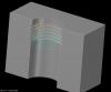
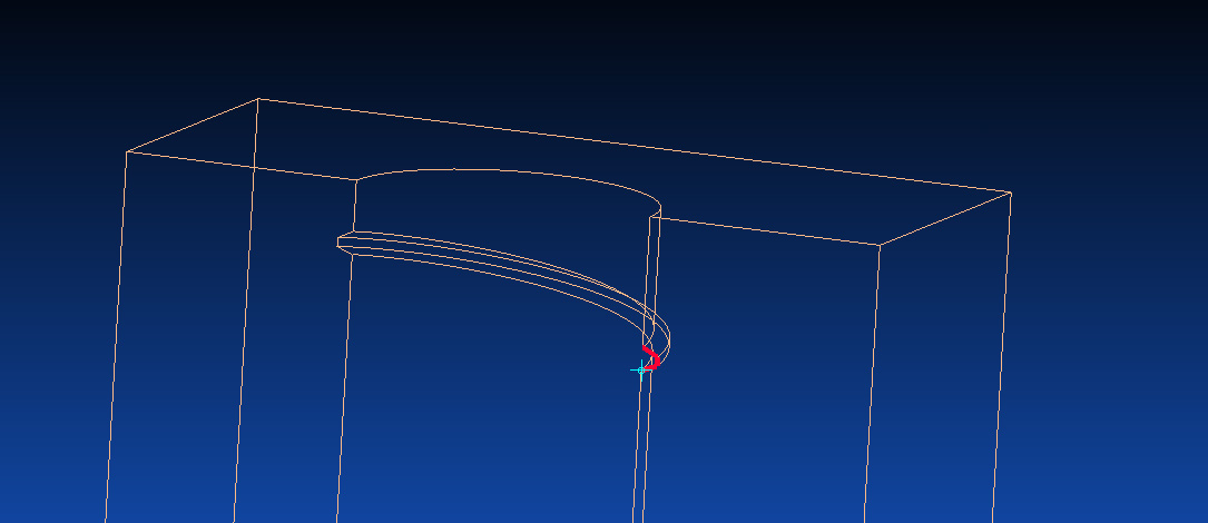
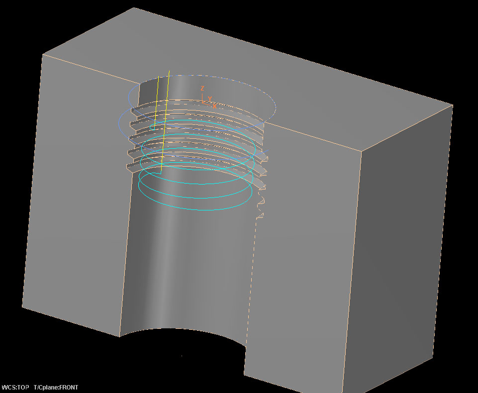
We use simple 3D chain contour, since the start and the end have to be on the right position (lead in and lead out).
The overcut in the verify is the same as measured on part on the measuring machine. The math is what I need to figure out.
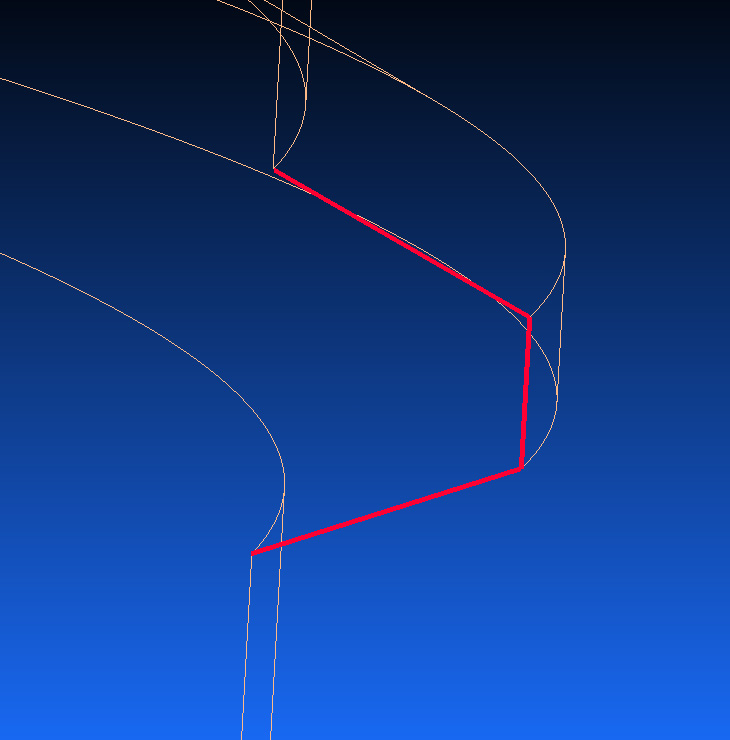
If the diamter si X and the angle in y and the diamter of the millin cutter Z, how do I define the right profile for the cutter so that I don`t get overcut
-
Hi
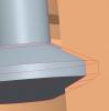
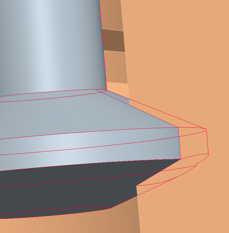
I`m having a problem cutting custom thread on my 3x mashine. We are talking about mold form threads, not functional threads. But it also has to be within +-0.02mm/wall (polished surfaces)
Usualy I create a thread milling cutter from thread profile, I do a rotate profile.
This usualy works fine if the thread pitch is small (2-3°) and the diameter of a thread is big enough. In some other cases (large pitch , big angle, small diameter exe: angle 30°, diameter 12mm, triple thread on 120°)I get overcut on the angled walls (top and botom). I solve these problems with test cuter in aluminium.
My guestion is: is there a way to define a thread cutter, so that it dosen`t overcut. Mathematicali, geometricali, practicaly....
other files can be send to e-mail if asked!
thanks


-
Draw a half profile of your custom tool to actual size.
It can be on a level in your file or a stand alone mcx file.
Create a new tool.. choose "undefined" as the type. Set the level number or navigate to the
defining mcx file.
The outline of your new tool will apear in the window.
On the parameters page set the diameter.
If the tool has a corner radius be sure to set it
in the corner radius field.
Use the tool as you normally would
It will backplot, verify and post properly.
I also use custom tools to cut inside and outside threads in mould forms (closures, caps, shoulders...)
I have an additional question:
The cetters are always shown in backplot but NOT always in verify.
So I can not always compare stl with the actual form of thread.
Whay is that. I draw the profile in the separate mcx file, on x0.y0.z0
questions:
do you draw a centerline of the tool?
do you connect the bottom of the cutter with x0.y0.z0?
do you save the file in the same folder with toolpath or in mcamx/mill/tools...?
do you draw a cutter in the samo file on a different layer?

-
First try Ram saver, in case something is left behind, else, you should start all over again, new file. From the beginning

-
Draw a containment!
-
I have the samo problem in X4MU2 on Win7 with Quadro Fx 1500. When I draw lines or arcs I get all kind of graphic trash on screnn (white squares, toolpaths used to be on screen....)
What would be the best setting for Nvidia card, or where would i get the configuration for nvidia control panel settings!
-
usualy it is an error, becouse you had pirat copy of mastercam na that comp. Only solution is format.
Check older posts. Use search!
-
I have tried one thing. Firs importing IGES file and then proengineer part file. Proe worked and Iges didnt!??Figure!?
-
I have tried all that as well. Mybe the problem is in my AMD Athlom X2 procesor. I have heard that there were some problems with athlon and Multi-threading!
-
yes I can, send me your e-mail address!
-
The problem is not in the parameters. For instance, I can create raster toolpath in SHS or with old toolpaths with the same parameters. They both get calculated, but the SHS toolpath is 0.2kB big, and nothinh in it. No error is reported.
Sometimes it helps if I restart computer, or if I start programing part from begining!
-
the point is, that no mather wich tooplpath i choose from SHS. i get nothing!
-
When I use Surface High Speed toolpath for milling I get : Toolpath - 0.2K. If I use Old toolpaths everything is working OK.
I have tried replacing config file, reinstall .net, reinstal Mastercam X4...
Any ideas?


VPN and Nethasp
in Industrial Forum
Posted
stop firewall