


swanny
-
Posts
60 -
Joined
-
Last visited
Content Type
Profiles
Forums
Downloads
Store
eMastercam Wiki
Blogs
Gallery
Events
Posts posted by swanny
-
-
Wow! Thanks a lot guys. I will let you know how it goes.
-
Yeah i knew that was coming
-
 1
1
-
-
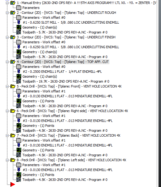
I want to clean up all the stuff in my post. Not sure if some of this can be done. This is the generic haas 5 axis rotary post that I'm trying to edit.
1st: I would like to remove date , time, mcx file, nc file, and material from notes.
2nd: I would like to remove all all the details from my tool list and just leave a cutter description and tool number, also be done at tool changes.
3rd: I would like it if my manual entry didn't split my 1st tool description and my toolpath comment. If possible I would like for it to be after my tool list
4th: I would like to get rid of the brake going on and off at each tool change and only go on and off during rotation.
If i can get rid of any of this it would be much appreciated. Thanks in advance for any help.
-
Never mind. Found it in an older post about the same topic. It was in the post and not the machine definition.
brk_mv_head : 1 #Break the 5 axis moves to remove gouge
brk_max_ang : 180 #'brk_mv_head' maximum angle move, applied if chordal_ "was 1 changed to 180"Fixed the issue-
 1
1
-
-
Depending on what program your using to make that toolpath you may have your max rapid movement set to 1 deg.
In your linking settings the angle step for rapid moves may be set to 1.
Just a thought.
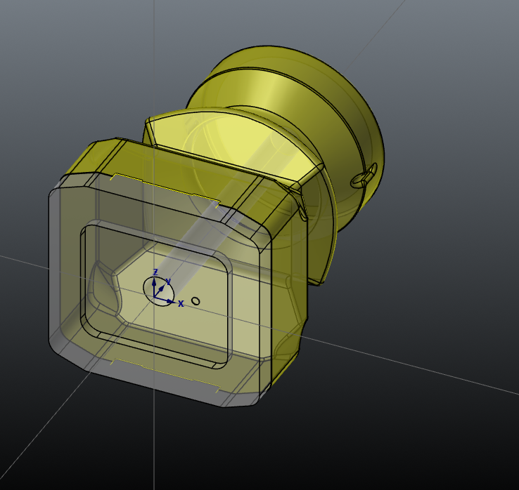
Its just 2d contours. Not a surface program. I think its a machine definition or a post issue.
-
My post wants to do a bunch of b axis moves instead of just rotating 90 degrees. It only happens when the rotation is with the same tool. If I force a tool change then it works fine. attaching a picture of the posted problem. Running mastercam 2017 - haas vf2- tr series 5 axis trunnion mill.
-
There was a bug in the installer. It has been fixed and is working fine FYI
-
1
-
-
I can get the non English version to work but it seems like the English version isn't extracting the files.
-
Does any one here use it for mastercam 2017? I installed it and added it to my toolbar but cannot get it to run the tool list sheet
-
Go into your post and look for this
use_frst_wcs : yes$ #Use only the first WCS read and ignore all others in NCI
You'll want to set that for no
Personally, when I program for 5 axis, I prefer the 1 offset unless for some strange reason I really, really need another but if your setup is good, 1 offset should be fine
Thanks. I will look for that. If I was running one part like this I wouldn't bother with multiple offsets. But its easier to control during a run of 100 parts or so.
-
I have a few toolpaths with G54 and a few with G55. I have the planes set to a G55. I also go into my operations manager and set them there as well. When I post them together, G54 and G55, all toolpaths post as G54. When posted separately, they post correctly with the designated offset. No idea why. Generic haas 5 axis trunnion post, Mastercam X9.
-
My question is why do you want to have this be A0 and not let it do it the proper way were it will rotate to the A-90 then you can move from there. Did you set the machine control on G55 to A-90 and lock that as A0 now?
Thats what I wanted to do. But I guess I'm just going to let it do its thing. Just thought there might of been a way to program just the B axis to move.
-
Because I have helix entry turned off
Be careful defaulting to this type of toolpath. If you use a single point threadmill all will be good and you won't notice anything. But using a multi-flute threadmill, this will create a 1/4 turn of flat threads. I made this mistake already. That is how I know.
-
I would set your WCS to TOP (A0/B0), then make your C/T Planes rotated as you need. Post up a file if you can. The trunnion Haas post is pretty solid out of the box.
I originally tried doing this. I will post it up to show what I'm getting.
-
gwizard cnc cookbook works pretty well. I like their material options too.
-
I do threadmilling a bit different than you do.....I select the arc....
I created a .500 diameter arc, used a .250 dia tool and set 2 cuts at .02 and a finish at .005
N112 G0 G90 G54 X0. Y0. S1000 M3
N114 G43 H1 Z.25
N116 Z.1
N118 G1 Z-.25 F25.
N120 X.0389 F5.
N122 G41 D1 X0. Y-.0625
N124 G3 X.0389 Y-.0736 I.0389 J.0625
N126 X.1125 Y0. I0. J.0736
N128 Z-.2 I-.1125 J0. <--------------
N130 X.0389 Y.0736 I-.0736 J0.
N132 X0. Y.0625 I0. J-.0736
N134 G1 G40 X.0389 Y0.
N136 X0.
N138 Z-.25 F25.
N140 X.0398 F5.
N142 G41 D1 X0. Y-.0725
N144 G3 X.0398 Y-.0827 I.0398 J.0725
N146 X.1225 Y0. I0. J.0827
N148 Z-.2 I-.1225 J0.<-------------------
N150 X.0398 Y.0827 I-.0827 J0.
N152 X0. Y.0725 I0. J-.0827
N154 G1 G40 X.0398 Y0.
N156 X0.
N158 Z-.25 F25.
N160 X.04 F5.
N162 G41 D1 X0. Y-.075
N164 G3 X.04 Y-.085 I.04 J.075
N166 X.125 Y0. I0. J.085
N168 Z-.2 I-.125 J0.<------------------
N170 X.04 Y.085 I-.085 J0.
N172 X0. Y.075 I0. J-.085
N174 G1 G40 X.04 Y0.
N176 X0.
N178 G0 Z.1
N180 Z.25
N182 M11
N184 M5
N186 G91 G28 Z0.
N188 G28 X0. Y0.
N190 M30
All diameter cuts as I set them are output at the values I would expect to see.....
The I-.125 being final and leaving .005 for a finish cuts, that's .0025 per side so the last roughing pass would be at .1225
The I.1225 being the final rough pass and setting to 2 passes at .020 that's .010 per side so the .1125 pass would be correct
So your passes at .1125, .1225 and .125 are correct
When you use multiple roughing passes the very first path is a calculated distance from your finished number based on the ending diameter.
I'm not sure if I that explanation makes it better or worse
.gif)
If you really want even cuts all the way in......subtract your minor from your major, divide it by 2(per side distance) then subtract your
desired finish cut amount and dived the remaining by how many cuts you want......that value would then be your step over....
Thread milling does not recognize the anything but the geometry size to be cut
Why isn't there a Z move on line N124?
-
Haas VF-2 SS , TRT160 (5 axis rotary), Mastercam X9, GENERIC HAAS VF-TR_SERIES 5X MILL.MMD
I want to have my part rotated at the machine A-90. (part toward back of machine)
I want to set that as G55 A0. B0.
Now I want to program my part like that and only have it rotate the B axis. But it won't let me. It still wants to post out an A-90. , instead of an A0. Is there anyway to tell Mastercam that all I want to do is rotate the B axis? I want to rotate B 180 degrees about Y without moving A. I have my WCS at FRONT and my Toolplane and Construction at TOP for the first side. Then I rotated my WCS about my Y axis 180 degrees and saved that as a new WCS. Still have my WCS at FRONT but now my Toolplane and Construction views are set to the new plane. I thought that would work.

-
Here's my probe calibration program (for Fanuc)
%
O7001(PROBE TOTAL CALIBRATION)
(K:NCSYS\ENSHU GE480H\PROBE\AUTO-CAL192.NC)

(THIS WILL USE THE AUTO-CALIBRATION FIXTURE)
(FIXTURE OFFSET -- G54)
(XOYO CENTERLINE -- Z TOP OF RING GAGE)

M00(SET STYLUS LENGTH WITH A TAPE MEASURE)
(THIS PROGRAM MUST BE RUN ON PALLET A)

#5221=0
#5222=0
#5223=#921
#5224=0
G00 G17 G20 G40 G49 G80 G90 G94
M06 T04 (4" LONG PROBE)
G10L52
N6202R00000001
G11
M19

G54 X3.1 Y-31.5
G43 H04 Z13.
G65 P9810 Z11.3 F20.
G65 P9801 Z10.8425 T04
G65 P9810 Z13. F200.
G65 P9810 X.00317 Y-30.63638
G65 P9810 Z10.7
G65 P9802 D1.
G65 P9804 D1.
G65 P9810 Z13. F200.
M30
%
#921 is the distance from G28 Z home to the center of the pallet. We also use a calibration plate that attaches to pallet 1 and every machine has their own program.
Thanks for your help. Works great
-
Are you running Inspection Plus?
You should have a tool length offset active for your probe. You should be able to use G43 for your probe like any other tool. After your programmed Z command to activate the tool length offset, use 9810 for protected positioning.
ie:
M6 T151 (PROBE)
T1 (FACEMILL)
G0 G90 G54 X0 Y0
M59 (PROBE ORIENT ON)
G43 H151 Z2.
G65 P9810 F50. Z.2 (PROTECTED POSITIONING TO FEED PLANE)
G65 P9811 Z0. T1. (CALIBRATE FACEMILL TOOL LENGTH)
G65 P9810 Z2. (PROTECTED POSITIONING TO RAPID PLANE)
M58 (PROBE ORIENT OFF)
G91 G28 X0. Y0. Z0.
M6 T1
G90
M30
Why are you using G91?
Thats just it. I dont want to use a G91. This is what I was told how it was setup before. I dont like it. This is a haas control on a VF-2 SS. Yes it is inspection plus. The machined part is on a small fixture. The part has a really tight true position tolerance on it. So the probe comes down and touches off on the part each time, sets a new offset, then runs the machining process. They normally use the machine home location for a z location and, eyeball the probe to a starting point and then edit that in the program as an incremental move from the home position. works great until you arent in the home position, then it crashes.
-
I encountered something similar a while back on our Okuma MU500. It seems the Okuma probe macro cancels any offset applied, and moves incrementally from the home position. I wanted to position the probe using the length offset/work offset, and then probe locally.
From memory, I had to revert back to the base macro and programme my own probe sequence.
These movements are before the actual probing cycle starts though. Im going to test it out and see if this will work. I still want my probing cycle to work the same, Im just trying to give my probe a hard location to start from.
-
Not really. What I'm trying to do is have a z offset for my probe. So it references a workoffset for a z movement instead of assuming its at the home position and incrementally moving down. I crashed a probe because of this. Anyone know if I can just give it a different length offset not being used. So for instance my probe is tool #24:
T24 M6
G90 G54 G0 X0 Y0
G43 H34 Z5.
G65 P9995 W54 A11. D0.27 E-0.7
-
This has been the format for the probing cycle before we run a part. Its added to the front of a program so every part gets probed. The problem I just found was you cant start the program mid cycle because of the G91 Z- move. But as long as you run the program from the home position, it works fine. Need help to rewrite so I can start probe from anywhere in the program.
T24 M6
G90 G54 G0 X0 Y0
G91 Z- ( INSERT Z POSITION FROM HOME)
G65 P9995 W54 A11. D0.27 E-0.7
The other thing is the height offset for the probe is a set number. 5.5169 which is from the spindle to the tip of the probe.
Just need to be steered in the right direction.
-
Im pretty open to trying what ever you think. I will write toolpath and post a picture of the verfy
-
ok there is the scallop settings I was using


Nickel sulfamate
in Industrial Forum
Posted
Has anyone else milled nickel sulfamate? We are an electroforming shop and it requires we 2nd op machining a lot of plated parts. Mostly small parts. .375 in diameter and about the same tall. Looking for cutter types, sfm, ipt. Any suggestions would be much appreciated.