VINK
-
Posts
25 -
Joined
-
Last visited
Content Type
Profiles
Forums
Downloads
Store
eMastercam Wiki
Blogs
Gallery
Events
Everything posted by VINK
-
I was talking to our reseller about this issue and they asked if I have a second monitor connected periodically. I actually have a second monitor connected full time. It is behaving as if there is a hidden active window though but I cannot find it. Mastercam itself just keeps giving me the chime sound when I click stuff until I hit ESC to back out. Perhaps it's a Windows issue?
-
I have 50 Solidwork Files I'd like to batch convert to MCX files but I am having no luck. I go to File>Convert>Import Folder and then nothing happens. No prompt to select anything. I have to hit ESC to get out of there. Am I missing something simple here? Thanks for the help
-
I am the admin to this system. Folder was set to "read only" but it turns out the old X6 ops folder was also set to "read only" and I was able to export to it. I gave it another go just and it exported this time. Not sure what I did different but I'll chalk it up to not having enough coffee earlier. Thanks for the input
-
We have a job that we have been doing 2-3 times a year for the past 10 years. It is a series of plates with holes in various locations so it really helps to just import an ops file assign points, post and go. That what I have done for this job since version 9. The last time I saved this ops file was in X6 and even use that same file today with X8. My problem is that we finally needed to add one additional toolpath and when I went to export the operations to (shared mcamx8 / mill / Ops) it just doesn't show up. Am I missing something here? I even drug over the old Mastercam X6 Operations File from its old folder but X8 won't write to it. Thanks in advance for the help
-
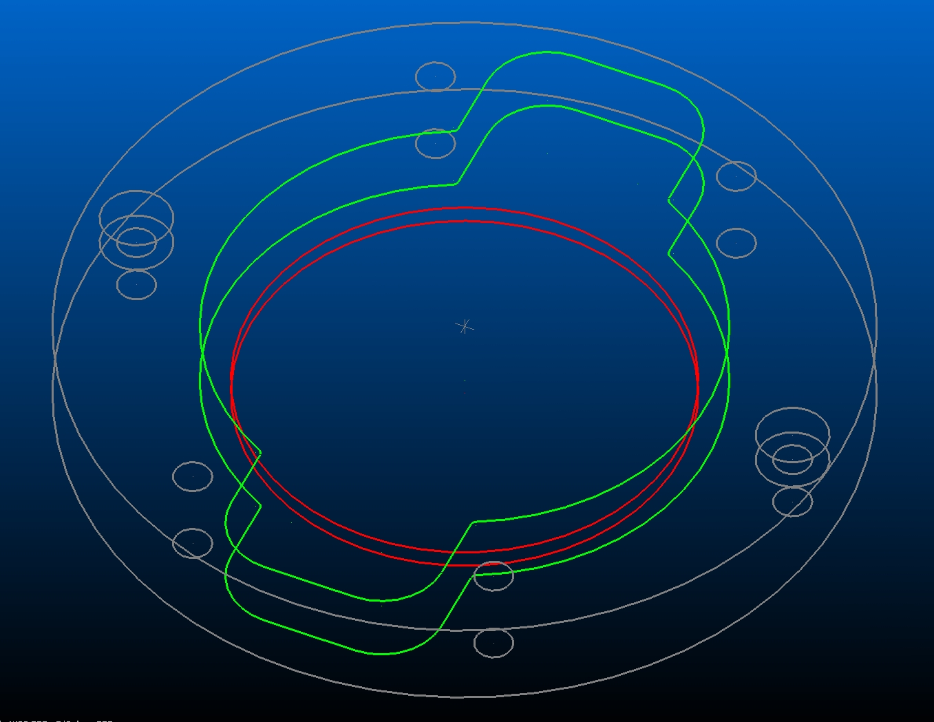
Thanks for the input guys, At first what I was trying to do was dynamic area mill the 1.75" hole first but did not want to use it again to do the pocket above because the majority was already cut. If I use some false geometry to avoid the center 1.75" hole it became a very inefficient tool path because Dynamic Area Mill approached it as a ring shaped pocket. That is why I figured if dynamic core mill could work inside out it would be a very efficient tool path. I ended up approaching it like you suggested initially Greyman, I Dynamic Area Milled the pocket first and then contoured the central 1.75" hole (should mention the part is 3/8" thick and the pocket is .300" deep so the floor is pretty thin anyway. I attached the pic of the part. Although this part didn't demand it I still think it would be great to use Dynamic Core Mill inside out. Again, thanks all

-
Hello all, I have a part that has a ~1.75" thru hole in the center of a non-circular pocket. How can I use to Dynamic Core Mill to mill the pocket after the thru hole has been cut. DCM would be the most efficient tool path if I could just figure how to use it inside out. Thanks in advance for the help.
-
EPS file conversion error "the resource file was not setup"
VINK replied to VINK's topic in Industrial Forum
Thanks Hockey Guy, I will give that a try. -
Hello all, I have an EPS file of an image that I'd like to open. However, I keep getting an error that states "the resource file was not setup". So how does one go about setting up an EPS file? Thanks for all help
-
That's the ticket right there. Thanks. Now my poor old computer gets to have workout converting all them!
-
Hello all, I just received a folder with 241 Inventor IPT files. Is there a way I can convert all of them (or any other file type) into MCX5 files automatically or am I stuck doing it manually? An alternative solution to my problem is if I can somehow preview geometry of IPT files without converting them. I really only need a handful of the files in the end for my project, I am just not sure which ones based on the file name. Any help is greatly appreciated.
-
This particular part is wireframe only. No solids, no surfaces. However, I'd like to print those too! I'll give the ol' reboot a shot.
-
I have started to have this issue where I cannot print my parts. I keep getting a warning saying"unable to generate shaded print, try a smaller print region and/or a lower dpi or change display mode to wireframe". Here the rub, I am trying to print just a wireframe of a very simple part, not even in color! So is this an issue with Mastercam, my printer (HP L7680 AIO) or the network I am trying to print over? Thanks for any and all help.
-
How to use a ket cutter to surface underneath a flange
VINK replied to VINK's topic in Industrial Forum
Okay, I'm officially lame and have to resort to hijacking my own thread...I am following the FTP upload instructions but when I drag the file from windows explorer to dump into the "X3_files" folder it prompts me to open the file that I am trying to save onto the FTP. Is this normal? -
How to use a ket cutter to surface underneath a flange
VINK replied to VINK's topic in Industrial Forum
I'll go ahead and post to the FTP if you guys got time....now to figure how to post to the FTP! -
How to use a ket cutter to surface underneath a flange
VINK replied to VINK's topic in Industrial Forum
So I got the normals set correctly. Flowline ignores the flange and blows through it and Contour seems to want to do both sides of the surface! I set a containment but then contour decided to just to the side of the surface that is not what I want. I appreciate all the help you guys are giving by the way. -
How to use a ket cutter to surface underneath a flange
VINK replied to VINK's topic in Industrial Forum
Since the shape is ring like I am using a radial tool path. I am still new to the X interface and I don't even see arrows indicating which side is the normal. I'll play with it a bit and see what I can wreck! -
How to use a ket cutter to surface underneath a flange
VINK replied to VINK's topic in Industrial Forum
Thanks Colin, I am still having an issue though. Although I selected the surface from the backside it wants to surface the top side. It's not clear to me how to select the bottom of the surface -
So I have this part that is going to have a KF Vacuum flange mill on it. The bottom side of the flange has a taper on it that I'd like to try and surface using a key cutter (actually I think it's a T-Slot cutter) that has 1/8" radii on either edge. I've never tried surfacing underneath anything before....can you do it? Will Mastercam comp to the uppermost edge? Thanks for all help
-
Thanks guys, It's been such a long time since I needed to do this that I forgot about selecting it in the verify menu. I guess I was thinking, since I am fairly new to not just X3 but the X interface, that setting it up in the initial stock definition would take care of it. Case Closed!
-
So I have this part that is a weldment. Just a simple square tube with a gusset welded halfway thru. I created a solid of the weldment and saved it as an STL file. Now I want to use the STL for my stock definition in the subsequent MCX file I am using to machine some angles and holes. The STL file displays fine except when it comes to verify....then my stock just turns into a flat plate no where near the dimensions of the welded part. How can I get my STL file to display properly in Verify? I am running X3 MU1 here. Thanks for any and all help!
-
Thanks gcode. Worked right away!
-
Hi All, So I've finally moved into the X era from V9. I have a solid/wireframe I've imported from SW. I deleted the original wire frame geometry so I can perform some edits to the solid and now I want to create edge curves again. When I go into create>curves>curves on all edges it prompts me to select a solid. The problem is that I cannot select the one solid I have on the screen! If I click enough times it does finally select the solid but I am no longer in the create curves command. What am I doing wrong? I have X3 (12.0.4.20) Thanks for any help
-
I've just had CIMCO DNC Max 5 plus editor loaded onto my shops PCs. When trying to set the default editor to CIMCO5 it kept picking up v4.32. Now CIMCO5 is loaded directly onto my C drive yet I noticed the old version was loaded into the mastercam commom folder. I tried to move 5 there but had cause a sharing violation. I also tried to select other in the default menu and then select CIMCO5 and that didn't work. I've even pasted a shortcut to 5 into the common folder but no luck. Is there something simple I am missing here or do I need to get the PC guy out again?
-
Thanks a million....Checking "from tool" in the job set up did the trick
-
I have this job which has a series of random holes from part to part. Simliar tool paths for everypart with the exception of placement only. I've set up an .OP9 so that I do not have to reprogram from scratch everytime. The problem is that when I import the .OP9 all my speed and feed are recalculated. Pecks, dwells and every other value remains the same though. How can I get this to stop! Thanks...