


Guyinthedesert
-
Posts
376 -
Joined
-
Last visited
Content Type
Profiles
Forums
Downloads
Store
eMastercam Wiki
Blogs
Gallery
Events
Posts posted by Guyinthedesert
-
-
For cobalt drill i trying :
s=250 f0.5 inch/min
Feed sounds a little slow. Try .90/1.20 ipm. Are you pecking? If you are, don't.
-
I usually use "transparent" with shading to see inside a part. Then add dimensions or analyze point or distance, etc.
Thanks for the tip. I just tried it and it's quite helpfull.
-
I have some hole I am drilling that are very deep. We start with a jobber length drill then, go to two longer length drills.
I was wondering if there is a way to start drill #2 and #3 at the last drill point but retract to the top of the part. G code would be easiest.
Only way I've found to do it is to disable canned cycles in your post. Then it will post longhand.
-
Get yourself 'normal' to the compound angle and cut the part away with extrude or sweep. I like this in both SW and MASTERCAM because you have edges you can analyze 'ore measure to'. When your done suppress it or delete it.
I've done that. However, on this parts there are over 100 intersections. It would take way too much time to make a cut for each one. That's what's so nice about SW is that I can just scroll through the part in any plane or angle in a few seconds.
I also tried Solid layout, way too imparactical for what I'm trying to do.
-
I've been drawing up a model for a valve body with a gazillion intersecting holes. Is there a way in Mastercam to view cross sections of the part so I can verify drill depths and intersections? I usually import the model into SW, their section view function works great. I don't see why MC wouldn't have something similar, but if it's there, I can't find it. (something like the scissor function in verify, only in the main graphics )
-
Good morning Ladies and Gentlemen,
I have, and I hope a relatively easy question, that a few machinist here at work cannot figure out. If so, is it possible to delete geometry, without deleting part of the solid or model????

Any info or help will be useful, thank you for your help!!!!

You can run the user application Nohist.dll. This will remove the tree from the solids manager. You can then delete or modify all the geometry without affecting the solid.
-
When do you use multipasses? how do you calculate what #'s to fill in for roughing and finishing and how much the spaces are?
As an example, if you want to leave a finish cut of .010, set the parameters for 1 rough pass, spacing 0,
1 finish cut, spacing .010
For each additional roughing pass you want to make, add a pass number, and the spacing the offset you want.
when do you use computer compensation?
The difference between computer comp and wear comp, is that wear comp introduces the tool dia compensation,
which you would almost always want. If your doing a 2-d toolpath, there's little reason not to have it set to wear.
On 5 axis surfacing, you would probably want it set to computer.
When do you use no compensation?
When you want the toolpath to follow the exact geometry lines. Such as engraving.
when to use lead in/out?
Almost always, unless you want to rapid into your stock. Lead in/out with a linear line is also a must
for turning tool comps on and off correctly.
when to use break through?
Say your finishing a hole in a part. You will probably want the tool to feed though past the bottom of the stock to avoid having a lip at the bottom of the hole.
when to machine face?
The face milling toolpath is a real easy and relativly efficient way to rip the stock down to size.
when to use depth cuts? how do you figure out max rough step, finish cuts and finish steps
when to use wallpasses?
Most tools won't cut an entire part in one pass, therefor you need depth cuts. The step down you need depends on a multitude of factors.
I had to take a long break from school, and sadly I forgot alot of the basics.
Thanks so much!
Was it so long you forgot that A Lot is two words?
-
I am trying to create a custom tool profile for a small single-point thread mill. I've managed to do this several times in the past, but when I select the file with the profile, I get a warning message that says "Problems with custom tool file or data". I've checked the chain for gaps and different Z levels and all the usual stuff, but Mastercam (X3) won't let me use it. I've even tried it with and without the centerline. Makes no difference. Any ideas here? File is attached.
You've got two bogus lines off to the right of the tool. Delete them and you'll be good to go.
-
That satement is not correct. It actually does start at the min value on the steep shallow page. If you have 20 mm stock above your Z zero than enter 20. for min. Enter your max depth as a negative number. That being said it may be faster to use a face mill to hog off all that extra material.
I stand corrected. I tried a test cut, and it didn't cut the top of the part. Turns out I had the Stock to leave set too high. I would still opt for the Face mill to rip the stock down.
-
try setting min/max values on the Steep/Shallow page
In surface high speen roughing, it starts at the top of the solid, regardless of the min/max values. I would just use Face to knock the stock down
-
Yes, but the only way I've found to do it it a bit of a pain. If you look in the MachSim folder, you will find a folder for each of the defined machines. Inside each folder are a set of STL files, one for each machine component,
an .XML file, which is a text file defining each component, and a Gif file with a picture of the machine.
Make a copy of the Folder from which you want to Rotate the 4th axis from, such as 1_4AXGEN_VMCTA, and rename it something else. In this Folder, rename the .XML and the .GIF files to the same name you gave the folder. In order to flip the Rotary, open the files ending in _A1 and _X3, these are the Rotary face and the Rotary Base. Rotate them 180 deg and save as the same name.
Now, open the Files ending in _X1 and _X2. You need to move the table down so the rotary is at the other end. I think I moved mine -21.000 in. (BTW, when I first opened mine, everything was metric, but suddenly everthing went to inches and I'm not sure what I did. )
Now, open the .XML file and invert the X axis limits.
I'm not sure yet how to get the .Gif picture right.
Now, when you open Sim setup, your new machine will be on the list.
I also scaled my Rotary to make it look more like an 8in than a twelve. Worked good, except when I scaled it, it left a gap between the rotary and the table so I had to move all the Base, X and Y features up in Z.
-
I am still having no luck with this issue. My arc settings are good to go.I do get wire frame to post out arcs. I have created a cylindrical ruled surface using 2 arcs and still the same results.
Any more ideas?
Thanks
Jim near Boston
Under Total Tolerance, is your filter setting on with Arcs enabled?
-
Go to your Control definition, under Arcs, make sure Arc output is enabled
-
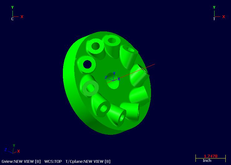
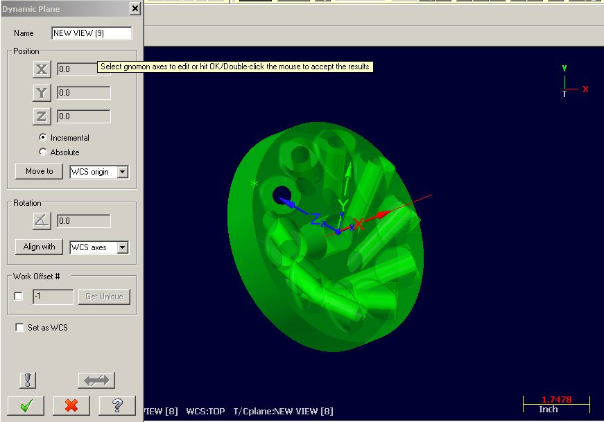
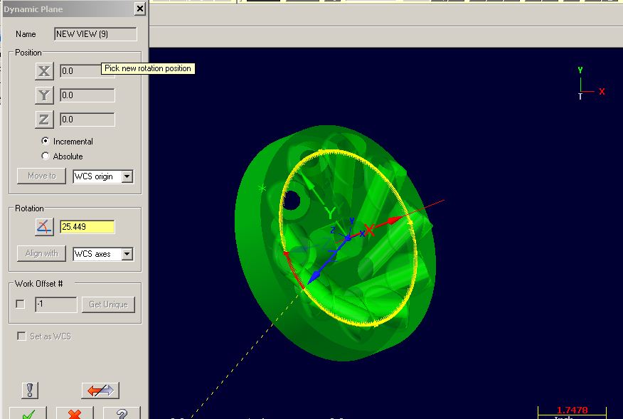
I've attached some screen shots to better illustrate what I'm trying to do.
I can't post the actual part I'm working on, so I drew up something to demonstrate.
In X1.jpg, Here is the part with one of the bosses rotated around normal. I'm going to run some 3 axis toolpaths on a 5 axis machine. Let's say, I'm just going to drill the one hole. (ten plcs)
So I have this rotated with the hole straight, and saved this as new view [8]
Now I want to rotate my view around the line going through the center of the part 36 deg to get to the next hole.
In reality, I could just put my toolpath in a subroutine, and just rotate C axis at 36 deg intervals. But for the purpose of verification and simulation, I would like it all done in the file. (The actual program is a lot more complicated than drilling a hole)
X2 shows dynamic plane with the gnomon set at orgin
X3 shows the rotation around X, just as I want. I almost feel like I'm on the right track.
This view is saved as new view [9]
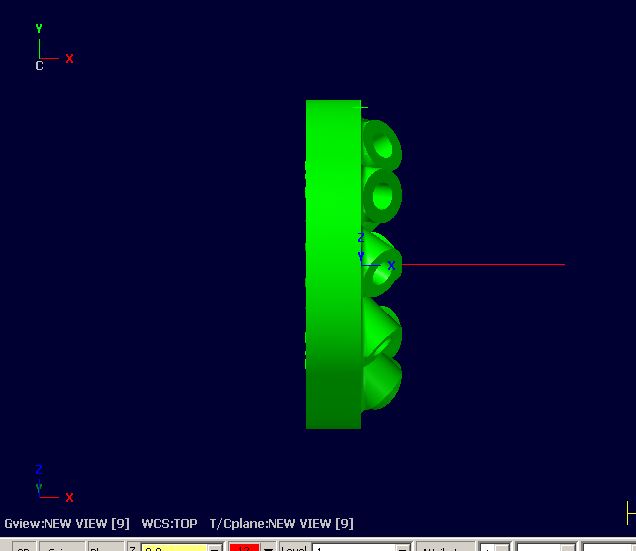
x4 But, when I go to view [9], it's rotated back straight to the Top view. It does the same thing whether I have
the WCS set at Top or new view [8]
Any Ideas?


-
Are you referring to the Z normal of the plane you have associated with the toolpath?

Actually no, I want to rotate the part around the X axis of the Top plane (Z axis of the Right side)
while in my defined TC plane.
-
Not sure if I understand what your trying to do but if your going to use dynamic rotate to put the gview into the postition you want for your new planes, once you get it there just hit the one in the pic below.
Right. But I don't know what angles my view is rotated to. If I did, I could go back to my right side view, rotate that view in Z, then rotate about X and Y go get back to where I was. But without knowing those angles, I'm lost.
I went to view manager and got the matrix values for my view. I can use dynamic translate to rotate the matrix values around, but once again, it will make it straight, but not tell me what the angles were.
I tried using Dynamic planes. I looks like this is what I want. I can align the gnomon, then rotate around the Z axis at what angle I want. But when I save it and go to that view, it is always rotated straight with the XY axis,
no matter what options or settings I use.
I drew a dummy flat surface at my TC plane, and then rotated that surface around in Z on the right side plane to my other angles. I choose View by entity, and that worked creating the other views I needed.
(problem was, I translated a toolpath. It translated the geometry just fine, but all the cuts had the same TC plane,
so the first cut on the top of the part was fine, the cuts on the bottom of the part it tried to cut through to top of the part.)
I think the dynamic planes is what I want. I must have something set wrong.
-
I have a part where I need to keller a floor, and to reach it I have my TC plane rotated up and around at a compound angle. Now I want to rotate my plane around the axis of the part (which is normal to the right view).
I used dynamic rotate to find a view where I had clearance for the cut, and made this my TC plane.
I know I've done this before, but I can't remember how.
-
I'm trying now to run Machine Simulation on a five axis program for an impeller. The program cuts one blade, than we use toolpath transform to cut the remaining blades.
Simulation just skipps over the transform operation. Is there any way to make it run?
I can choose the copy option in the transform, and it does create a toolpath that Sim will run all the way around, but, for obvious reasons this is not what I want to do.
-
Have you tried Suface High Speed Core Roughing?
-
for custom tools, you will have to draw the holder in with the tool for machine sim to work.
Thanks, that did the trick. I cropped in the "Holder.mcx5" file from tools, and deleted the spindle taper and the
centerline. Only minor glitch, now when I open the tool def box, in the tool display window I can only see the holder and not the end of the tool.
-
I've just been working with machine simulation and finally I think I've gotten it all figured out. However, I just tried to simulate a new program, and it skips over all operations that use a form tool, all of which are defined on various levels. I don't think there's a problem with the tool geometry, as I can run Verify with no problems. When I try to run simulate, I get an error "Holder profile must have different heights for the last two points" ???????????
Does mach sim not work with form tools? That would really suck, as this program has 12 of them.
-
Hi All,
Any ideas? I have tried an STL and a solid as Verify stock, The result is the same
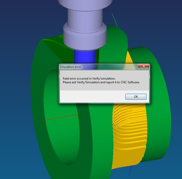
I recently encountered the same problem. It turned out that on one toolpath, going around a round boss, I changed the startpoint so the lead in/out would be on the left side of the boss instead of the right side. That was all it took to make it crash. I then rotated the circle that I extruded the boss from 180 deg. Problem solved.
WCS Question
in Industrial Forum
Posted
Also, if you're going to use machine simulation, you need to translate the vise (and/or fixture) to the position of the part, so you would need a separate vise for each op that uses a vise.