


megaman
-
Posts
36 -
Joined
-
Last visited
Content Type
Profiles
Forums
Downloads
Store
eMastercam Wiki
Blogs
Gallery
Events
Posts posted by megaman
-
-
Thanks agian colin that is very helpful as always-
-
 2
2
-
-
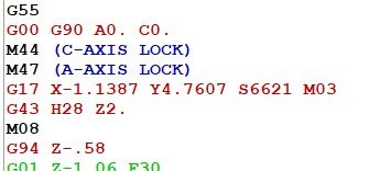
I have been programming for a number of years but only getting into it full time in the last year. I recently programmed a part and missed the offset default of G54 in my program, and it made it to the floor and crashed! on the machine I programmed it uses G54 as a home to store the center of rotation for the trunnion "A" and "c" .
The only time we should see G54 on the machine is when we use dynamic offsets
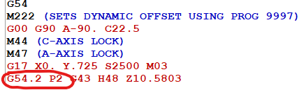
When looking at a lot of code I missed that it was supposed to be G55 without any dynamic offset since this was when I didn't need any tilt or rotation .
G55 is my WCS. having this as a default would have saved me.
Thanks for any feedback or constructive criticism in advance!!
-
There are so many options to click and try.its not easy to get clean paths all the time. Like anything else it takes time.
CONGRATS! and yes thanks Colin !
-
2
-
-
On 2/24/2021 at 9:36 AM, Colin Gilchrist said:
You can set the Geometry Size to 0.0000, using a G10 line, or using Macro Variable Formulas in the NC Code. Just wanted to point out that there is a method available to make sure the Operator doesn't miss making the change. In fact, you could 'save the current Geometry Size in a Common Variable, reset the Size to 0., and then restore the Size when the Operation is finished', all by using Macro Variable Formulas.
In fact, if you want to adopt Wear Comp as a standard, you could make your Post output G10 Lines in the header, to clear out all the Geometry Size values, to avoid the issue of an Operator forgetting to clear those values.
I have never been a fan of Full Control Compensation, and feel like any shop who still uses it as a standard, is basically still living in the dark ages. No offense intended...
Hi Colin,
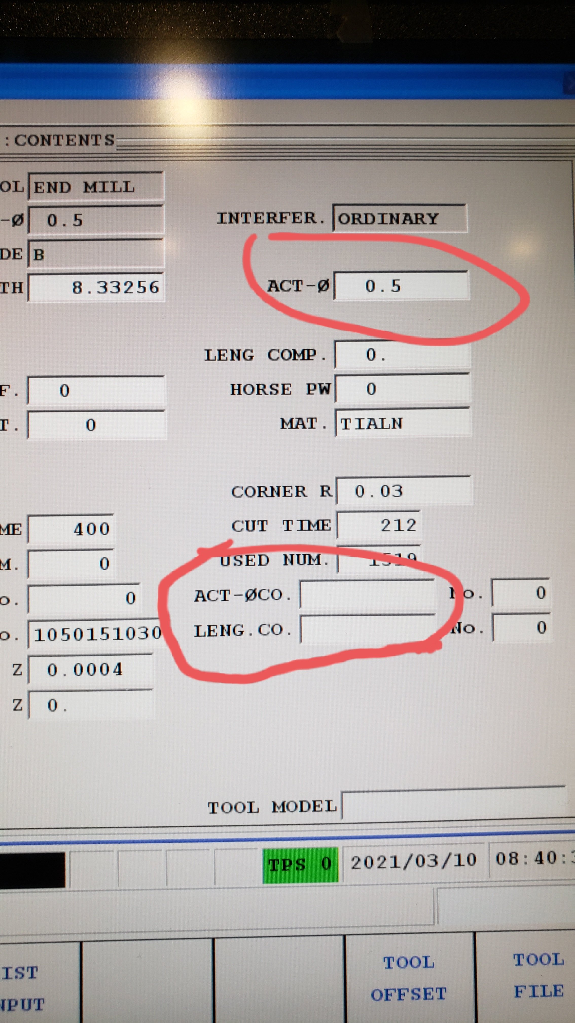
I am looking through the manuals to try to figure out the G10 line I would need to writ into the code to be able to do this. Right now we are using the Control comp and both Mazatrol and EIA read the Actual diameter to adjust the amount of compensation. Typically if we have a 1/2" endmill and the hole is .003 small we will have the Actual diameter at .497 as an example. Actual diameter compensation also can adjust this but can be missed easily by the operators since that is down near the bottom of the page of blanks.
Can you give me an example how I can use a G10 line or macro to either include in the post or macro that i can somehow add either manually or thru Mastercam to output to get around not having to go through retraining all the operators to input the correct data.
I find the information in the manual somewhat confusing on which parameters to change and if we would still be able to think in terms of diameter and not going back to a radial offset mindset.
Any insight or clarification would be greatly appreciated!

-
4 minutes ago, Colin Gilchrist said:
You can set the Geometry Size to 0.0000, using a G10 line, or using Macro Variable Formulas in the NC Code. Just wanted to point out that there is a method available to make sure the Operator doesn't miss making the change. In fact, you could 'save the current Geometry Size in a Common Variable, reset the Size to 0., and then restore the Size when the Operation is finished', all by using Macro Variable Formulas.
In fact, if you want to adopt Wear Comp as a standard, you could make your Post output G10 Lines in the header, to clear out all the Geometry Size values, to avoid the issue of an Operator forgetting to clear those values.
I have never been a fan of Full Control Compensation, and feel like any shop who still uses it as a standard, is basically still living in the dark ages. No offense intended...
Thanks for that Colin, I will look into moving over to wear and using G10 to do so . What are the advantages of using wear .
No offense taken I respect your feedback and just want to improve.
-
32 minutes ago, crazy^millman said:
Well the issue is Mazak and the EIA/MAZATROL control of the tools if the machine's parameters have been set to use the MAZATROL side of the machine then you may only need the TOOL number and the D number is implied to be read. Again depending on the parameters.
What you show in that picture is probably not having simulate Control Comp on in the back plot parameters. Turn that on and that backplot will look correct. The last issue I don't use Control Comp I use wear. Just ran a program in an Integrex Yesterday and we ran WEAR with no problem and hit our desired bore since within 1 micron. Helps then run the machine in Metric mode, but I couldn't believe we hit it that close.
Easy way to test is to take a test block and cut a hole. Then adjust the wear comp on the machine and then see if ti gets bigger it does then you don't need it. If it doesn't then add the D value manually and run it again. If it then adjusts the size that is your answer and you send that code to In-House and they will get you fixed up. Mazak's are parameter driven machines more than just about any machine out there and depending on the way the parameters are it has a huge effect on the way EIA runs on the machine.
I am not 100 percent sure about the mazatrol/eia settings but we use the actual diameter and then change that to a smaller size to get it to go bigger on internal features.
SIMULATE backplot was on and it still does that .
If I was going to use wear I would manually put in an m00 and tall them to make sure actual diameter is zero and use actual dia. comp to get to size. most operators just know how we normally do it.
-
2 hours ago, So not a Guru said:
No G68.2 on the machine? Or no G68.2 in the post?
22 minutes ago, crazy^millman said:No Option bought for it might be the case. They support G68.2 with their G68 with no issues. Question is do you have the right post and have you do the correct testing of that post to vet it for your machine?
Hi guys,
you are correct it may be that we just don't have that in our post. I have been programming this machine for years but only diving into the full 5 axis more that I have ben programming full time. I haven't had issues with this post too much but I'm sure I need post refinement. we do use g68.2 on our head table machine (VTC800). the multiaxis threadmill in drill (with control comp gives me the result below.- we always use comp to avoid changing and having operators input the wrong diameter) I was only able to get it to work by creating a plane an then using a 3 axis output and then transforming it .
I am trying to find out whether this is a Mastercam issue or a post issue I need Inhouse solutions to modify my post. I don't see a D value and it sees to cancel at the wrong place.
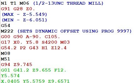
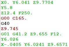
Any knowlegable input is greatly appreciated!!
-
1 hour ago, PAnderson said:
How does Mazak get away not having G68.2 on a 5 axis machine?
By using g54.2 p.... dynamic offset
-
Yhis machine is a table trunnion machine . A mazak variaxis 730. No g68.2 on this machine.
-
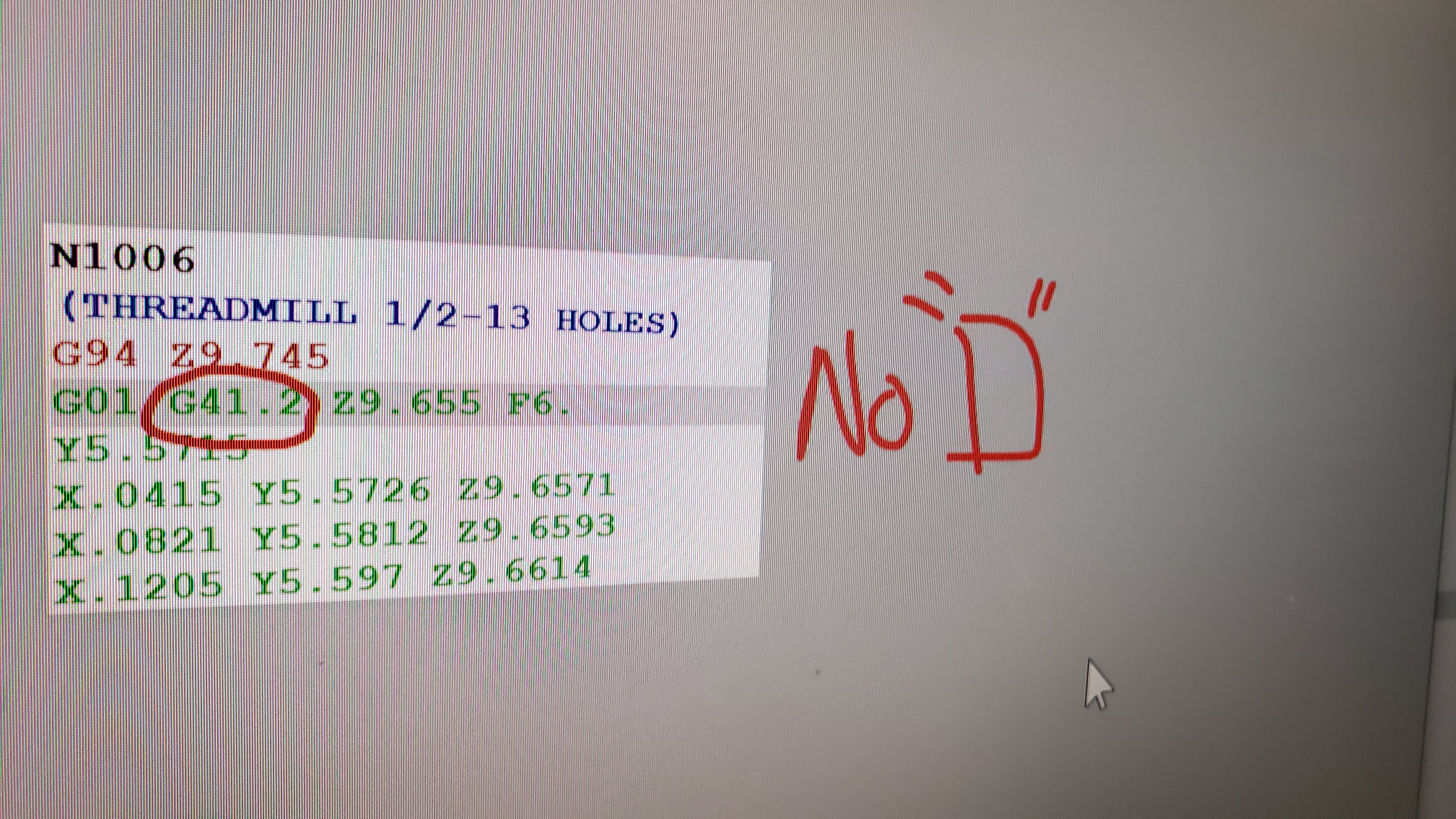
I used drill-5axis threadmill and tried to output with control comp. It shows the tool arcing to the middle of the cutter on the edge of the hole. I coukdnt get control comp to work. Is thread milling with 5 axis output a no-no?
-
Hello, can anyone give me some sample code using g41.2? Is it not nessesary to hae a D value in a g41.2 line or do i need to fix the post?

-
Good day everyone,
Recently we have been discussing going to Inches per revolution for everything. Being a primarily Mazak shop the mazatrol always has this. When using a software like mastercam there is a misc. Value that will convert all the feeds.
Does anyone know of any negative aspects to this. Besides confusing shop staff.
-
Thankyou so much crazy mill man. I had many pmeshes over other stls.
-
Crazy mill man, you keep refer to saving to pmesh and to a level. Ive tried the save stock to pmesh...nothing happens.. i also dont see anywhere that gives me options to save to a level then i can delete the toolpath and not have dirty operations the monent i change a simple perameter
-
Originally a few years ago creating a duplicate tool was inhouse solutions(our reseller) answer to the problem.
Now we use transform a lot and often create copied tools with the same tool number. Creating tool lists or set up sheets using active reporting or Varco set-up sheets becomes cluttered and confusing.
There's got to be a solution for not duplicating tools
-
We use kennametal end mills the most and they are great , we've used imco,harvey iscar, emuge , osg, sandvik, and hanita. We like kennametal the best for a we range of selection , cheaper than that of high end with reliable performance , osg comes in a close second for the same reasons as well as their website and catalogues are really user friendly.
-
We moved over from fuchs to Ometa . Its much cleaner and the parts and tools come out with almost no residue at all.
-
i would like to do somthing as simple as use a 1 " insert endmill to plunge out a slot.
I see the plunge mill in surface rough but what if i dont have a surface is it possible to select a line and tell it to plunge along that line and specify the stepover?
-
crazy , i would have never thought of using multisurf on a 4 axiseven though i do exactly that tool path with 4 axis output on my 5 axis.
good stuff
-
That video changed the programs of so many parts in our shop already. The more dynamic it gets the more we save on tooling. We go through a huge volume of endmills.
-
We are a medium sized shop that is allowing all the mill guys to use mastercam (9). We have both x6 and x7 installed on our computers. So many of the guys are frustrated with x7 verify and its dependability.
Is there or can someone at cnc software make a video on how to use this and compare with accuracy. Right now i have been playing with it for months intermitently and still cant get the results like x6 .
-
Please send a link to the exact tool you are using off the tool manufacturers website and I will see if i can do a vid.
http://www.iscar.com/eCatalog/item.aspx?cat=3105246&fnum=2592&mapp=ML&app=75
this is the cutter.
i tried to edit the dfx file in mastercam , again i couldnt figure out how to edit the file and make it usable.
what steps do i need to do to make this usable for verify and be able to see the tool and get an accurate output of what the part would look like?
thanks again
-
i am trying to make use of all the info here but putting it all together and getting mc to use and show the tool definition does not seem to work. just reverts back to a flat endmill or gives me an hourglass shape.
What hapened to ASPE
in Industrial Forum
Posted
Does anyone know what happened to aspe on YouTube? He put some if the most intense video tutorials of muliaxis. Now the chanel has no content. Did it get moved?