


Thee Awbade™
-
Posts
179 -
Joined
-
Last visited
Content Type
Profiles
Forums
Downloads
Store
eMastercam Wiki
Blogs
Gallery
Events
Posts posted by Thee Awbade™
-
-
You need to export/Inport your "customize" settings, while you have the drop downs/right mouse button menu open I believe.
That being said, it never really works quite right for me so I end up re-making it every time I re-install/upgrade
-
So, I'm going to be Machining a 4.3 Lb Foam core by DIAB.
I've machined these parts once before using an 8 fluted carbide cutter (that I regularly use for composites milling, complete overkill for this.)
I got a bit of melting/tearaway on the finish of my core. Looking around the internet I only seem to see brochures/advertisements for this stuff, and not any reccomendation on what to use to cut it.
I'm going to be facing, as well as cutting strips/pieces out of this material about .438" thick, in 5 axis with a 5 degree draft to prevent jig-lock.
Basically what I'm asking for is a reccomendation for a cutter to use to machine this material, as well as maybe a feed/speed suggestion (Max IPM on my machine is 250 IPM, 20,000RPM
-
Mark, do you work at PPG Aerospace? I think I've done some work for you
-
Interesting. I've only worked in 2 places so my experience is much much more limited.
I was told at my first job by a boeing engineer that it was like a sacriligious sin to move models out of airplane coords, and they act pretty much the same way in my current shop. I wonder what the difference in attitude is coming from
-
on the surface it sounds nice, I just don't think that's practically, the restriction is necessary
But that's me, I've been doing this a LOONG time and seen reasons for everything.
If my contract or PO stated it, I'd live with it...Doesn't mean I wouldn't be shaking my head though
.gif)
Yeah, I guess I'm just used to it since I've always been doing it (Outside of my first month on the job or so.) So it's not as big of a deal for me. It sure looks nice not having to work around that though =P
-
I have NEVER understood the aversion for some companies to moving parts..it's location within the CAM has absolutely ZERO to do with anything upstream.....
If someone told me I couldn't move a part I'd tell them they were effin' crazy
and those who know me, know I would
But, you can very easily move the origin to your part and work around it
I'm pretty sure it has something to do with compatibility between contacts. So if I'm working on something and wanted to send off my changes for someone to compare to, the two parts would be in the exact same spot. (Also, for aerospace we call it "Airplane Co-Ordinates" Because if you were to merge all the files for a specific project, they fit exactly where they are on the plane. Actually looks pretty cool when I merge all my files into one mega-file and I have a huge airplane!)
-
 1
1
-
-
Yes I did Jay
Learned a few things from that video, thanks for makin' it J!
However, in the Aerospace Industry, it's HIGHLY frowned upon to move actual parts. So for me, no matter the orientation of the part I cannot move it, or change it's location in space in any way whatsoever. Is this not a standard practice in most fields? I notice you transforming/moving the part quite often (I'm going to use some of these tricks for simply moving my toolpath geometry however.)
-
Talk to NilsN. He has a Quintax Router that is about 12 years old, and uses a F@gor controller.
I learned on that machine, however I didn't mess with the post much.
We exclusively used MasterCAM On it. And I know he runs that machine now.
-
Honestly I find that the machine simulations don't take those into account. You would need to look through your Gcode to see if the code is actually calling out for it because you might never see it in the simulation.
-
Had to clean up the solid since I don't have solids, converted to surfaces, created drafting, went to front view. Broke drafting into lines, projected lines onto inside surface of ring. Selected just lines and transformed them to be slightly in front of the ring so you could actually see them.
You're talking something like this ya?Ended up looking like so.
-
I don't have X6 but I tried out your paths on X7,
OP1 = about 2-3 seconds
OP2 = About 3 Minutes
Both seemed to work fine though.
I changed the total tolerance on OP2 from .0005 to .001 and it reduced my time down to about 20 seconds
-
Yeah it is a carousel tool changer. I'll be giving them a call tomorrow to hopefully solve this. We thought maybe it was the sensors on the servo bar for the A Axis but after messing with those we've learned that we just don't know what we're doing, best to leave it to the advice of pro's tomorrow morning. I'll update y'all with what I find out
-
You might have to contact the machine builder, the thing with the F@gor controller is they allow the machine builder to use their own error codes, so you won't find the code in the F@gor manual. Is the machine a DMS or Motion Master by any chance?
It is a DMS. I'll look in the DMS manuals
-
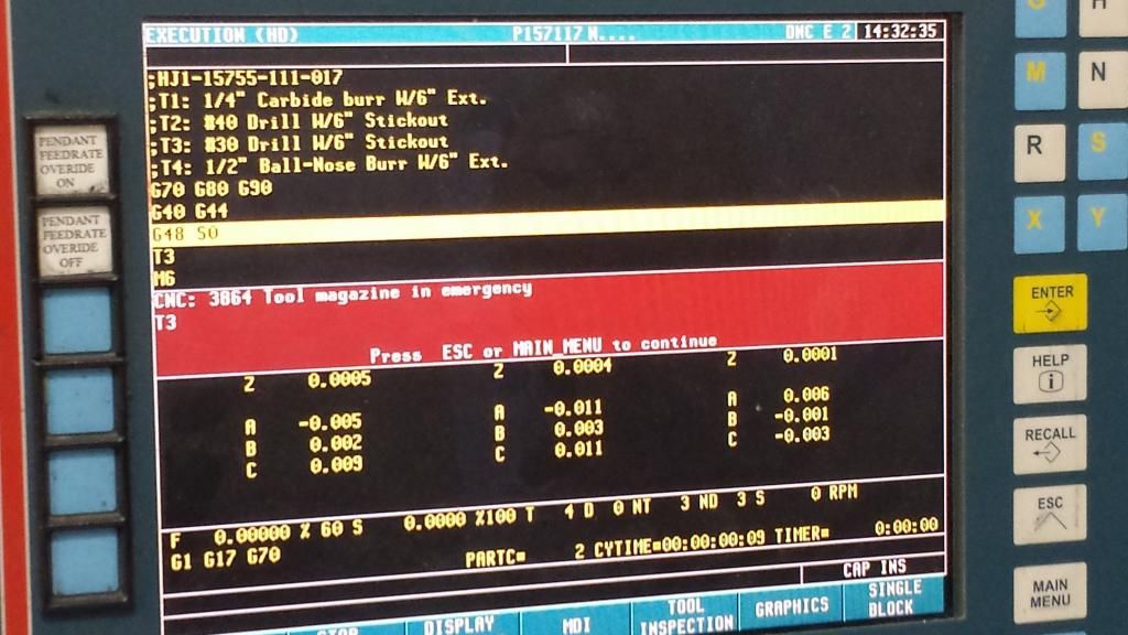
So We recently had a machine problem here with the hydraulic cylinder on the Z Axis. We got that problem solved but now anytime we try to change tools with our automatic tool-changer (A Axis). When we command to change tools, the controller pops up with error message "CNC: 3864 Tool magazine in emergency"
At this point we've checked:
air pressure
Reference searched tool changer axis
any signs of stutter or stoppage on the tool changer
restarted machine.
I've searched the internet for my error code, but it doesn't exist. not even in any of the xxxxor manuals.
Really need to get this machine up and running pronto so any ideas or suggestions, i'm glad to try out.
Here's a photo of the error code.
-
I'm cutting some Nomex Honeycomb Core, went out and bought one of their 75CH-6 Line cutters. .750" Diameter, 3" Length of Cut, 6" Overall Length.
any Experience with these in Nomex?
What types of finish surface can we expect on a flat surface using the bottom of the cutter, or on a horizontal wall using the profile of the tool?
-
Save all of your offsets from presetter to a txt file program. Use G10 command in the text files for your offsets. Send the text file to the CNC control, then execute the program just like a regular nc program. More info can be found in any fanuc program manual.
 If you desire the old and inefficient way of doing so, consult with Crazy Mill Man. He is old.
I gladly welcome your programming suggestions, however that would not work for my current situation.
I'm looking to have it go through the subroutine every time, to verify that the #'s are correct. We run on a 10x15 foot machine, therefore things move, and offset values change within a half-an-hour.
I'm also not on a Fanuc, I'm on a F@gor. Are the two controllers very similar? I've only ever programmed or used F@gor controllers
Please keep the insults/fights/i'm better than 97% of you out of this thead if you could. I'm not looking for a de-railment here, just trying to figure something out thanks =]
-
Hmm. Perhaps I should clarify a little bit then.
Currently my setup sheets say "X0,Y0 At Center of bushing. Z0 at Table Height"
Operator uses Coax center-finder to find center of bushing. Takes tool out of spindle, uses 1,2,3 block to determine Z Height where Z0 Is the spindle nose touching the table. Input all of these numbers into the work Offset Table under G56 to which all of my programs are programmed. He then goes with all of his tools in the carousel and types "M101, Cycle-Start" And the machine goes to the automatic tool-setter, touches off on the tool, records tool length. Rinse and repeat through all tools. M101, M102, M103, M104 etc.
My Code looks like this
%,100001,MX,;450-061-504-117 Program
;T4 #30 Drill W/4" Stickout
;T5 #40 Drill W/4" Ext W/3" Stickout
;T10 1/4" Burr W/3" Ext
;T11 .215 Drill W/ 4" Stickout
G70 G80 G90
G40 G44
G48 S0
T10
M6
S16000 M3
G4 K300
D10
G48 S1
G56
G51 E0.01
G0 G90 B62.454 C-91.039
What I WANT to do is put into my code something like
%,100001,MX,;450-061-504-117 Program
;T4 #30 Drill W/4" Stickout
;T5 #40 Drill W/4" Ext W/3" Stickout
;T10 1/4" Burr W/3" Ext
;T11 .215 Drill W/ 4" Stickout
G70 G80 G90
M100 (To Measure Z0 and auto-record it as Z0 for G56 Offset)
M104
M105
M110
M111
G40 G44
G48 S0
T10
M6
S16000 M3
G4 K300
D10
G48 S1
G56
G51 E0.01
G0 G90 B62.454 C-91.039
So that I take all of that human error of measuring Z0 off the table out of the hands of our operators.
-
So, I don't use much automation or even canned cylces within my controller or programs.
However we've had an issue lately with operators not properly gauging the height of the work offset we're using. (usually it's just the height of the machine table.)
I'm looking to automate this, using an auto-matic tool setter and wondering what types of things I should be reading into. We use a F@gor 8055 controller on a 5 axis DMI Router from 1999.
My Main concern is, when I set the work offset system to the tool-setter, how can I program an adjustment into that?
some of our older programs instead of using the table height as Z0 for our Offset, instead use the "Center" of a construction ball on the fixture which would be an exact 1.5" Off of the height of the table.
Essentially I'm looking to add into the existing code files some sort of command to have it use the automatic tool setter, to measure spindle height in G56, add 1.5" to the height and automatically record that as Z0 for the G56 offset.
Is this possible? If so, where should I start looking to find the resources to do this?
-
Wrong again. Religion is the root of all evil. Money only bankrolls it.
Haha, you don't know where you are!
-
Haha I've been doing this 2 years now. I think I could out-program.......0.001% of you all!
TAKE THAT!
(Oh, and only on 5 axis routers..)
-
1
-
-
I just went thru this with an older f@gor. check page 206 of this manual
Looking at this one, I realize that some of my other parameters are at the extreme as well, thanks for the info!
-
MM Thanks, I think I found the parameter just searching through the machine.
Each Axis individually has a parameter (I think it was P38, not 100%) that said "G00FEEDRATE"
Some of my axis were at 15,000 IPM Feedrate...That explains a lot.
-
I'm trying to figure out what parameter to change on our xxxxor 8055 Controller to modify the maximum rapid feedrate. Currently it's too fast for us, and occasionally when it G0 Rapids, it will move too fast and throw an axis error from the sudden movement.
I've found this PDF, but can't seem to find out where it says what the command is to change the G0 Feedrate
http://www.xxxxorautomation.com/downloads/manuales/en/man_8055t_prg.pdf
-
Oddly enough, I was just using it yesterday and it worked fine...and ran across this post. I did have to unshade the surface in order to pick the point tho.
Yep. Just walked out and helped our inspector do exactly this with the surface I made this post about. Worked perfectly.

Proper way to set WCS
in Industrial Forum
Posted
Well we could either go with everything relative to the exact center of the Earth, or the exact center of the sun. However; both of those are only relative to our Solar system.
We COULD map the entire universe and demand all cad models be relative in space to the exact center point of the universe. I'm pretty sure that's the one he's mentioning as regards to a "true" wcs