killall-9
-
Posts
56 -
Joined
-
Last visited
Content Type
Profiles
Forums
Downloads
Store
eMastercam Wiki
Blogs
Gallery
Events
Everything posted by killall-9
-
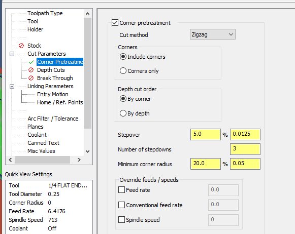
Hi Guys, Im using Dynamic Mill to chisel out some .375 rad corners with a .125 rad tool with no luck for pretreatment...
-
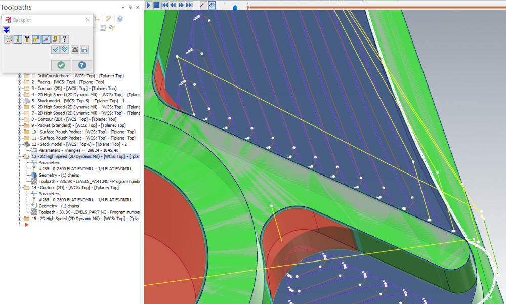
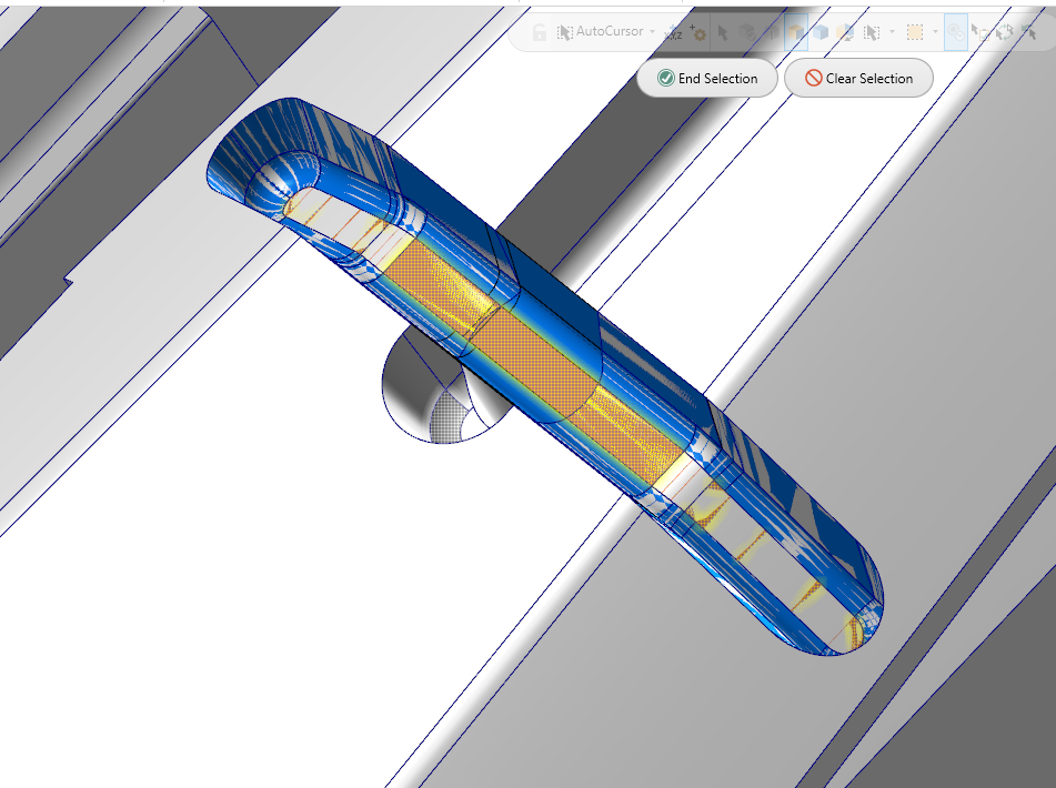
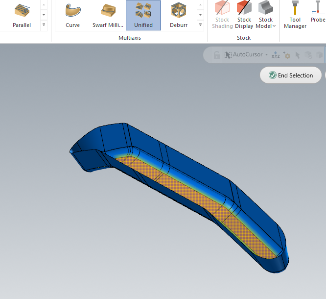
HI guys, Im not sure why the tessellation ends up like this. I had to stitch that slot/channel together bc of a thru hole below it. Could this be it ?
-
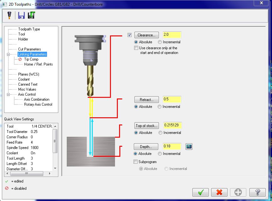
I wasn't able to pick up the bottom of the hole i had to measure it and manually put in the inc depth. Im not sure how you did this. I was able to get the correct depth, but its the same depth for all holes.
-
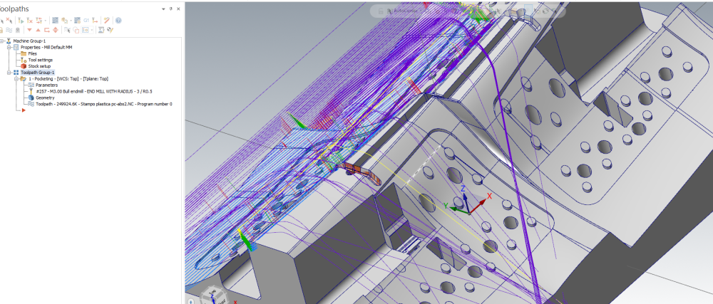
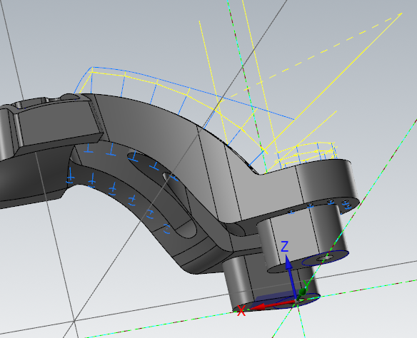
Hello attached is a photo of 5 AXIS drilling. I wonder if the depth of the hole operation can realize the new depths per hole. obviously it realized all the holes with a CTL+ Dbl click, but can it realize the changing depths as well ? In the included photo none of the hole are thru holes, but yet they are the same depth from the surface start point.
-
Can anyone send a sample program from their OT post processor ? showing canned, simple and auxiliary code structure ?
-
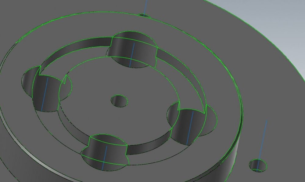
Hi Guys, Aside from 2 different contour ops, what would your opinion be to achieve this machined circular closed pocket?
-
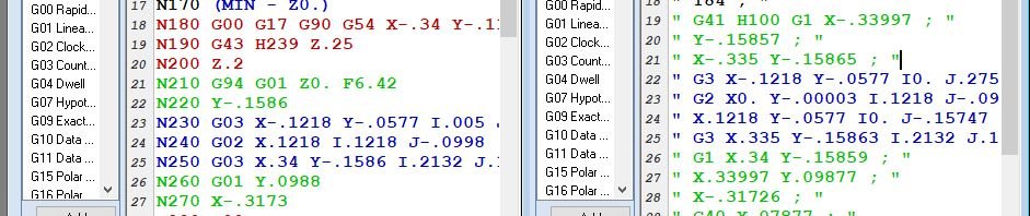
Hi Guys Not sure if this is a POST related issue or software. My EDM mastercam is producing code for radii in 90deg increments, so if it is a 180 deg cut, it breaks the code up into 2 different arc movements. I've shown an example of how my mill would produce and my wire. also how can i scale down the decimal shown from .xxxxx to .xxxx
-
Hi Guys, Another question on this. I was succesful with the info shared here. Many thanks ! A knitpick question tho: I am writing another program with Surface Rough Contour op dripfeeding at 9600 baud :( is there a way i can have mastercam spit out R / I / K values for turning corners on my toolpath instead of lengthy xy coordinates ? or is this redundant
-
Jlw, Thanks man ! last question, how can i start off the part, im new to this operation and as you can see i extended my lines to do this.
-
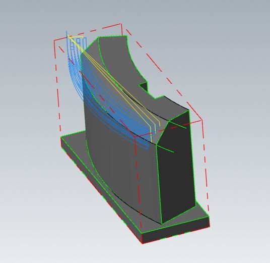
Hi Jlw, when attempting to only select the curved chamfer surface, it auto selects the whole part..
-
Hi Guys, I cant seem to get around this op selecting my whole part, rather than a surface (which is the curved chamfer surface) Ive selected the imported IPT as the solid material. Am i missing something ?
-
Hello, I would like to pull a 2D sketch from a STEP 3D model for programming (Lathe) purposes rather than a blueprint. Is this possible ?
-
Well i notice in my subprogram the R value is set to wrong which is different from the intital Rapid dimension: e.g. G00 G17 G90 G54 A0. X-.0123 Y-.156 S1800 M03 G43 H3 Z2. T16 M98 P0001 O0001 G91 G94 F4. G98 G81 Z-.32 R-1.5 F4. G80 M99
-
Hi, Im doing a Toolpath Transform 'rotary selection' to bascially duplicate 10 operations around a circle in the A axis. The code is great (subprogram) except for one thing: It sends the Z home (G28) after each index of the rotary which is specifically what i dont want. I want it to rapid up to a set retract ( Z 2.0) be it incremental or absolute. Is this possible in the options, or is it a post mod ?
-
Does anyone have a sample file or advice on using the Iscar face grooving tool MIFHR. I was told there is a certain grooving action you can use to do an intial plunge, then turn x+ and x- from that point.
-
Hello, just wondering why the Change recognition shows my old model still. X6
-
Hello, my post mod is fairly simple i believe. X6 i need the post (MPLMASTER) to spit out a G59 on ANY line where there is a change of feedrate, It currently only does it on the first feed change after any tool change. So if there are multiple feedrate changes in any given tools op i need a G59 on the line. Thanks very much for the help !
-
Great thanks very much.
-
I'm using a VCMT 1 rad insert to finish a profile, i can not figure out why the code is being generated incorrect. The tangent point of hte first radius is .048" but mastercam is spitting out .063" i have tried changing the tool compensation direction but no luck. Can anyone figure out whats goin on ?
-
I'm wondering your inputs on the best method of machining a recess on an endface of a part im trying to turn on the lathe. I've been told a i need a specific face grooving tool matching the largest diameter i will be starting at.
-
Well i guess magnified that much it just wont show it physically touching, i did get it by breaking the line going upwards on the 45 and making a point.
-
Im not getting anywhere , it wont trim or extend the line to the intersection point, thus i cant put a proper chain together.
-
As soon as i do the line extension in breaks the intersection as well.
-
No they are not
-
Here is what ive found. I am working with a DXF