ccs86
-
Posts
27 -
Joined
-
Last visited
Content Type
Profiles
Forums
Downloads
Store
eMastercam Wiki
Blogs
Gallery
Events
Everything posted by ccs86
-
With you 100% there. Lacking continuity between identically labled options within different toolpaths is lazy. Displaying options that have NO functionality is just as pointless (ie. check geometry in any high speed toolpath). In my mind, you should be able to give a high speed (roughing or finishing) path ALL of your geometry, as a reference for collision avoidance (this would include any fixtures you've chosen to model); then select one, multiple, or all faces as drive geometry. Roughing ops would look at the stock boundaries or rest parameters to calculate where it will remove material, finishing paths would assume a roughed part and just follow the drive faces.
-
Are you saying that you use containment boundaries to create avoidance areas instead of containment sometimes? Absolutely, it makes sense to me that you can create a closed chain, then then tell MasterCAM to either stay inside, or outside of this boundary, and it should do so.
-
By improvement, I hope they mean "actually functions", hahaha. It works great in OptiArea, but is buggged out in OptiCore and Core toolpaths. A boundary isn't a subjective thing. There is no legitimate reason to move the tool outside the countainment boundary (unless above the clearance plane I guess. Would be nice if that was optional as well).
-
There are two major roughing toolpaths in MasterCAM, Core and Area. This part is a core part in my eyes, just with hard boundaries on two sides. I did a similar part in the beginning of this thread, and had to use area roughing to avoid nasty collisions. I ended up with a FAR less efficient toolpath. On this exact same model, I generated a core roughing toolpath in CamWorks, gave it the same boundary, and it came out perfectly right away. Here's the file, just change the extension to .IGS 450_link_actuator_v2_CAM.txt
-
Well, I tried creating the raised planar surface, selecting it as drive geometry, then excluding it using steep/shallow z-limits... and bingo. I got what should have been created with ONLY the containment boundary. This workaround will get me there, but it's a pain. Since I'm rotating this part with the 4th axis, I have to create containment boundaries AND planar surfaces for each operation set. Thanks for the suggestion, I just wish MC would get their software working properly!
-
You mean to create a surface everywhere outside the containment boundary, raised well above the part, and add it to the drive sufaces?
-
Thanks for the suggestion, but I've tried every option within that dropdown. I'm making a new part with a similar setup and am having the same issue again. Mastercam mostly obeys the containment boundary, but mostly is not good enough. I'm failing to grasp how such a simple option fails so badly. NO portion of a toolpath should exist outside of the boundary. After working with CamWorks a bit lately, I'm amazed at how it actually listens to the different avoid options without fail. Help!!!
-
Just read your post, haha. Yeah, it's a pain. I really like the Opticore strategy much better than OptiArea for my particular part... much more efficient cutting. No helixing needed. I understand that core paths move out to in, but that's no good reason to ignore boundaries.
-
Awesome. Thanks again! I set up the Back and Bottom planes as instructed, locked all Work Offsets to 0, generated NC code, commented out a few unneeded A0's and it ran beautifully. I didn't have the material yet, so I test ran the code with foam. Came out beautiful.
-
Which plane do I set the Work offset to 0 for? I tried it with all planes I use, but get errors about that.
-
Rotary Ninja, you are awesome! I'm going to work on this today and hopefully cut tonight. Thanks everybody for your help!
-
I did notice that the Back and Bottom planes have a reversed X axis orientation. Is that part of the issue you are talking about? Well, that is a little simpler. So, what is that rotary axis positioning for then? Thanks guys!
-
So, are you saying I should have a new WCS assigned for each orientation? I haven't used offsets before. What will setting them to 0 do? Does that keep the machine orientation correct when switching WCS? Nope, I'm a student. Why do you ask?
-
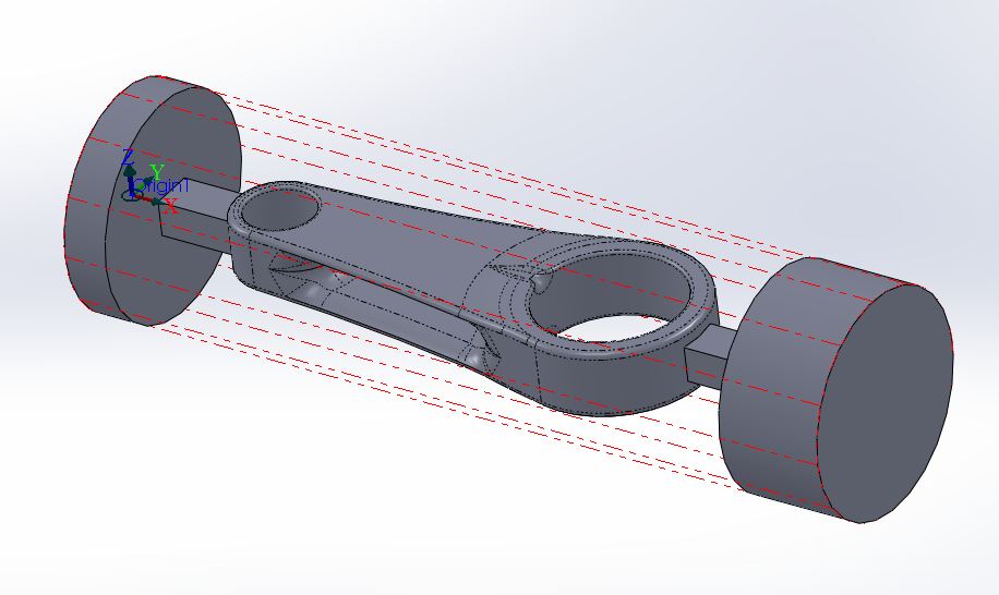
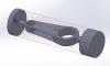
Hi guys, I think I'm on the right track here, but would love a little insight... I am going to manufacture a connecting rod, and to avoid multiple part setups, I would like to use the 4th axis and machine from round bar like this: My general strategy has been: - Start with WCS/Tool/Comp planes all set to top, do the top paths - In subsequent tool paths, change the Tool/Comp planes to Bottom, Front, and Back, respectively, leaving WCS as Top. - Also enabling Rotary Axis Positioning about X in each tool path. In verify, everything looks great. The tool attacks from the intended orientation for all 4 tool planes. However, in the G-code generated (Haas 4 axis, for use on a VF-2), I noticed something weird. It starts with A0, moves on to A180 (great), but the final two setups call A-90 and A-90 again. I was expecting an A90. Also, it seems to be creating a new WCS for each, ie G54, G55, G56. Is it possible that I can have everything coded in G54, just using A0, A90, A180, A-90 to index the part? Thanks so much for any help!

-
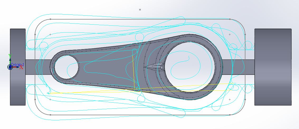
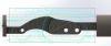
I guess you are saying that those cylinders should protrude inwards, past the containment loop. I've tried that. As far as stock goes, MC is aware that the stock spans the entire piece. I added additional model geometry that matches the stock at the ends, to help avoid the 4-axis jaws and maintain the part's orientation. This picture should show it better:
-
Thanks Brian! That makes sense I guess, since Core paths try to attack from the outside -> in. This part is a little of both since I like the core approach on the long sides (vs helixing into the the middle), but still need to avoid the short side boundaries. I switched over to OptiArea and am having no containment issues, though I have to let it plunge for each pass. Mastercam is just frustrating sometimes (most times! haha). I still cannot understand why the Surface High Speed finishing paths will not accept check geometry. If you only select a few faces that you want to finish as drive faces, the tool will go gouging through the rest of the part. Yet if you select the whole body, it wants to machine everything (re: lots of redundant cutting). It seems like a miserable fail to not allow you to make Mastercam aware of the entire part (for collision avoidance), and machine only select faces. Any suggestions on that?
-
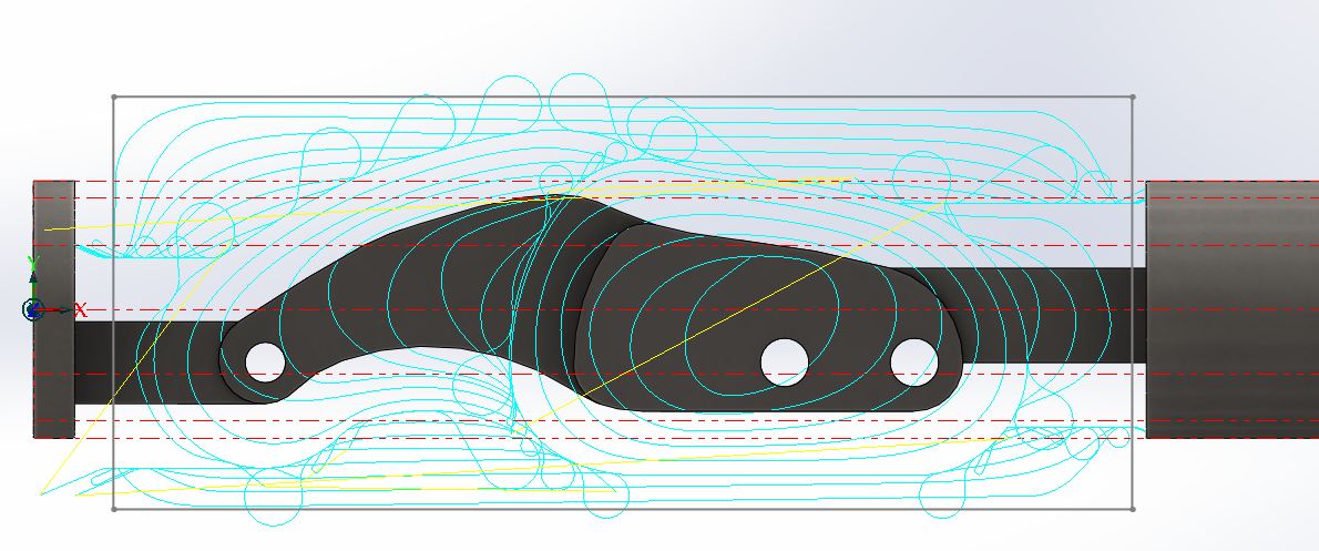
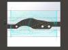
I'm not sure I understand. I would like to cut the part in the middle, as well as the square supports, leaving a nice smooth face on those left/right containment borders (from the first picture). I want it to completely avoid the two cylindrical faces, and that air space all together. Check out my second picture. I shrunk the containment boundary so that it is offset inwards of the off limits faces by the tool radius. Still no luck.
-
I tried adding a radius to the containment loop, offsetting the loop by the tool's radius manually, and selecting center containment. Here's what I get... I just don't understand, this seems like it should be very simple.

-
I have tried, but the surface HS tool paths warn that they treat check geometry as drive geometry. So, I give it the whole body as drive geometry. I've also tried omitting the faces in the offending cylinders.
-
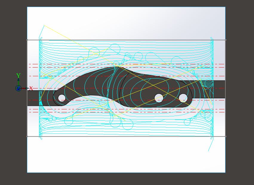
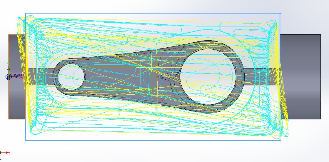
Hey guys, in need of some help! MCX6 has been really frustrating with containment issues. The latest example is using an Opticore surface HS tool path in Mastercam's Top view for my tool plane. I have a square sketched out on the top plane and selected as a containment boundary. I've tried outside, center, and inside (plus additional offset) for containment options. The majority of the tool path will remain inside the boundary, but without fail a couple portions will rip outside it. I really don't want to be forced to trim the tool path to avoid crashing the machine. Here's a picture to help: Thanks!
-
Thanks again for the help Motorcity! Much appreciated... I have been able to reduce my cutting time from nearly 3 hours, to just over 1!
-
Thanks for the help MotorCity! I'll have to explore back plot more. I usually just use verify. What benefits would you say back plot has over verify? I've also been trying to get machine simulation going, but getting things correctly oriented seems clunky. Let's say I've already trimmed that toolpath from the Z-up tool plane, to avoid the flats. I'm stuck there right? If I choose trim toolpath again, that same finishing path is not selectable from the list anymore. I tried adding the side view sketched chain to the original trim operation, but it gets ignored.
-
That doesn't seem to work because that radiused edge curls all the way under the part (look on the far right side of the picture). This seems to force those full depth toolpaths around the perimeter.
-
I'll admit that I don't totally follow what you described for using backplot to save geometry. Basically, I just created sketches in the tool plane that describe the floors I want to avoid, picked those sketches as trim selections, then chose a random vertex that was in the desired cutting area. This seems to work great for excluding regions in a top down, tool plane view... Is there any way to trim this same path from another plane's view? Here is a picture showing this finishing path. You can see the avoidance of floors (thank you again!), but I would love to avoid the area I bounded in red. A 5/8" flat end mill will have already cut this outer profile and I don't want the little 1/4" ball nose wasting time chattering around the outer walls. Much appreciated!
-
Surface High Speed (General) not found in your operation defaults file
ccs86 replied to Matthew's topic in Industrial Forum
Thanks so much! I had tried the Toolpath Trim feature once, but didn't correctly set the bias point. I went back and got it working... perfect!