


PKMills
-
Posts
34 -
Joined
-
Last visited
Content Type
Profiles
Forums
Downloads
Store
eMastercam Wiki
Blogs
Gallery
Events
Posts posted by PKMills
-
-
I was wondering the same thing. The new default "OLF SimpleSansCJK OC" font, like much of the drafting in 2022 is worse than it was. With this font the decimal point is a dot, which becomes invisible if you print a drawing.
I have the displeasure of having to do a lot of drafting in Mastercam and it seems that some things are not right in the 2022 version. I have noticed that when I change settings to make different dimensions, the settings don't stay the way I had them no matter what I answer to the prompt asking if I would like to retain the settings just for this session. It's very aggravating and time consuming to work with it like this. It was better in earlier versions and hopefully this will get fixed.
-
9 minutes ago, 5th Axis CGI said:
Are you making changes to the xml part of the post in CIMCO? You cannot do this and that will create exactly the issue your seeing. If you are making changes in the text section of the control this must be done through the Control Definition after about Version 2018. Before that you were okay making changes, but since then you must make any changes to the XML part of the post through the Control Definition.
If you see this in your post then this is your verification anything past that section cannot be edited in a editor. Make a copy of your old post again and then use the control definition to make the changes to the test you want then go from there and see if you get the same results.
# --------------------------------------------------------------------------
# POST TEXT
# --------------------------------------------------------------------------
[CTRL_TEXT_XML_BEGIN]  # Post text edits MUST be made with Control Definition Manager. The entire post must be encoded in the local code page plus the XML below despite UTF-8 tag.
<?xml version="1.0" encoding="UTF-8"?>
<mp_xml_post_text xml:space="preserve">
	<control>
		<control_label>CTRL_MILL|DEFAULT</control_label>
		<lang
I don't think this is the case because I am making edits to the text section of the post in notepad and that works. The other reason I think it has something to do with cimco is that if I make any edits at all, even adding an extra space to a comment and re-save, I will get the same result.
-
I've been having problems recently when trying to edit a post using Cimco.
Whenever I open a post using Cimco and then try to put it in the post file it's changing something that prompts me to update the post when I try to use it. If I click on yes to update, it freezes Mastercam at which point I have to force it to shut down and after restarting, every part file using that post will crash Mastercam until I put the old post back in.
I am able to edit the post using notepad but I prefer using Cimco so I can compare posts side by side.
Is this a setting in Cimco causing this? Has anyone had the same problem?
Thank you
-
41 minutes ago, 5th Axis CGI said:
Need to see if the post has a switch to cancel the G29 Z0 if not then you will need to have this logic added to your post to control this behavior. Look in your misc integers and reals and see if there is a switch for it. The idea with any post is to make the safest code possible out of the box then customize it down to each person Chocolate or other flavor of Ice Cream they want. Just about every machine will run Vanilla code, but then different people want the extra toppings or flavors and that is really what your post process can do, but problem is most people are sure how to get that flavor. The post teams doing that specialize in this understanding of what it takes to make the flavor of code you want, but they need your help to get it.
I guess they were out of butter pecan, because I sent them a Z2G and files a couple days ago and haven't heard back yet. I don't see any switches where I can edit one line and make it work, but then, I'm no expert at modifying posts. I'll just hand edit and wait until they get back to me or until I learn more about the post language to understand how to get the flavor I want.
-
9 hours ago, navsENG said:
Instead of translating it, copy your first path, re-select the plane (for the next rotation) and re-select the appropriate geometry associated with the plane.
That's exactly what I did for the ID toolpaths and I get a return to Z home between them. I suppose that has to be edited in the post, or use multiaxis linking?
-
That does seem to be my problem now. After each toolpath it gives me a return to z home position. I have created a plane for each position, but I'm not sure what you mean by individual operations for each toolpath. When I did toolpath translate and rotate I selected "create new operations and geometry" but I still get G91 G28 Z0. between each drill cycle.
-
After more trial and error it seems like I may have answered my own question. I created the geometry and toolpath in the back tool plane and then toolpath transform/ rotate/ create separate operations and turn posting off for the original back operation. If the features are not equally spaced I would create separate transform operations.
If anyone knows a different/ easier way of doing this your input would be greatly appreciated.
-
 1
1
-
-
Hi,
I'm new to programming for right angle heads. I've searched and can't find an answer to what seems to be a simple question.
I have a ring that has features on the ID and OD and we are using an indexer that's rotating about the Z axis on a vmc. I'm using an aggregate post that was supplied by our re-seller for this machine and I'm getting what looks like correct code by modifying the front tool plane and using the top wcs to get the proper rotation. The part I'm not figuring out is when it comes to drilling on the OD. It seems that in backplot it's always starting from the inside of that part unless I switch from the original front plane to the back tool plane.
In this case there are only 4 holes on the od that are equally spaced and I'm sure It would be easy to write out by hand but I would like to know how this is done in MasterCam 2019. I'm guessing there is a way to use the back tool plane and rotate, but how would you do that if the holes are not equally spaced?
Thank you.
-
21 minutes ago, david said:
(Tool 60 is my Probe
IF [VTLCN EQ 60] NSKIP
T60 M6
NSKIP
CALL OO18
G15 H1
G0 X0 Y0
G56 H60 Z-.3
(PMOD=6 OUTSIDE)
(PMOD=7 INSIDE)
CALL OO10 PMOD=7 PDI=.5
Z2
CALL OO19
M02Thanks David, but to be more clear, I'm trying to measure radii and not a complete bore. PMOD7 will attempt to probe 4 points of a bore.
-
Thanks for the info YoDoug! I may give that a try if I can't find a more simple solution since I'm somewhat of a newbe when it comes to Okumas and part probing in the machine. I wanted to use Okuma language if possible. I know there is a 3 point bore gauging function but I can't find the PMOD and related variables in the manual I have.
-
Can anyone give an example of how to write a macro to probe a radius for size and location on an Okuma osp-p200m?
-
Geil! Vielen Dank Günther. Weiter so!
-
Hi Jaanus
Another option you may want to look into is CAMplete. It simulates Gcode and optimizes 5axis toolpaths. I know it differs from Vericut in that it functions as a post using Mastercam's NCI file. I don't know if they have support for Integrex i100s but they do have a TurnMill product.
-
I could be wrong but I thought the first field in the tool def for threadmill asked for thread pitch. I changed from pitch to number of threads per inch and it worked. But I also noticed that any tool I had linked to a profile on a level now gives me a warning about "Bad custom tool profile source" "the custom tool's referenced file or level is not valid or cannot be accessed." Is there some way to avoid this? I have a tool library for these parts but I get the same problem when I try re-selecting the tool from the library.
-
Is this something that changed from beta 2 to 3? I already had the threadmill defined in this program with geometry from a level and the pitch and number of teeth were set. It seems to have lost the association to the level and won't let me use the geometry with the same parameters in the tool definition that was there.
-
I just installed 2017 beta 3 and in the cut parameters for a thread milling op I'm no longer able to enter a value in the number of active teeth field. Can anyone tell me if they are also having this problem?
-
The code looks like it's all moving in the same direction
I'm not familiar with this machine/control
is 2 feedrates on the same line normal??
N23 G1 X-5.5481 Y-2.7971 Z.1007 A3=.081 B3=.06 C3=.074 F100.;F6.
have you checked to make sure your brakes aren't cycling off and on with each line
on a Siemens control it won't read what comes after the semicolon.
-
Harvey Tool provides cad files of their tools.
-
1
-
-
Are you using inverse time feedrates? Have you successfully run other 5 axis toolpaths on this machine?
-
It sounds like maybe, if your machine supports it, you may need to turn high speed machining on.
-
Thanks gcode.
I can get to it by right clicking Op manager, which I never normally do. I still haven't figured out how to add a command to an existing group in a tab. I can only add it as a separate group. I also found that I can edit the context menu and add my most used toolpaths then right mouse button anywhere and select a toolpath.
-
I no longer see surface finish parallel in the 3D toolpaths. I suppose HS Raster does the same thing, or I can adjust parameters to use surface rough parallel the same as finish, but I used surface finish often and was wondering if it's hidden somewhere or if it has been done away with.
-
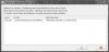
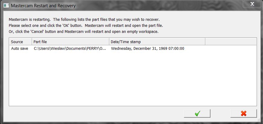
MasterCam crashed on me last September. I took this screenshot and saved it on my pc and forgot about it. I thought it was funny and figured I'd share it and see if anyone has any idea how I got this. The date is the day after my 2nd birthday, so I know I wasn't using MasterCam at the time.

-
When creating wireframe geometry in 2017 it appears there is no longer fields for entering x,y,z coordinates. If I'm creating a line endpoint or circle center point for example, do I now have to click a random point on the screen and translate to where I want it, or am I missing something? I realize this is something that I may not need very often, but I like the ability to type in an exact location for a point if needed.
Nevermind. Just figured out that although the input fields are gone, I can still type the coordinates in... duh
Drafting
in Machining, Tools, Cutting & Probing
Posted
The main thing I change in settings is hiding one leader and witness line to dimension one side of a turning profile of a large diameter part. I skipped from 2020 to 2022 and didn't seem to be having a problem in 2020. I suppose not many users do much drafting in Mastercam so it may be a while before it gets fixed. I'm looking forward to getting Solidworks so hopefully it won't be an issue for me much longer.