jbelle7435
-
Posts
58 -
Joined
-
Last visited
Content Type
Profiles
Forums
Downloads
Store
eMastercam Wiki
Blogs
Gallery
Events
Everything posted by jbelle7435
-
092613_02.MCX
-
maybe I got it this time...
-
sorry. I am losing my mind over this. Attached is the file. I have the line in there but I seem to be running into a wall every time. I just want the wire to come downwards from the origin, circle once, and come back. Can this be done in one chain because when I window it comes out to 2 or three depending and sometimes there way off or do something totally different than I expect. 092613.MCX
-
GOT THAT 100% GOT THAT 100% Not sure by this. How many passes. Would I want to take just 1 pass? Is there a setting for this offsets besides left and right spoken about earlier? that last part is ?? to me . Even if I have my compensation(LEFT< or RIGHT) and (CW or CCW) setup properly will this solve this because it sounds like not yet based on this Radius of wire+overburn
-
1.The origin of the circle or the origin of the plane? 2.What is the ideal way to select those in this case? channing,point, window,etc from the channing box. I been using window and sometimes it comes out good...
-
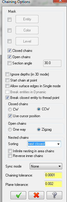
maybe something to do with these options
-
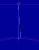
When I try to start my cut at the origin at the top it always angles towards the circle. I do the typical contour and added a line for the wire to follow but it still comes in at this slight angle. Is that normal or is there a way to make a path I am comfortable using prior to getting to the circle. I will see what I can find in the mean time if possible.
-
1. Great news for making strides with this. I created my 1st actual piece with MC and the WEDM! 2. Now its time to make sure what I want to make is represented by the code I use! One concern I ran into with the 1st piece coincidentally was about the discussion earlier in this thread about compensation. My program ran as CCW and the .5 hole came out to .520. Looking at the Code I inputted and USED for machining was G03 and G42. So the wire did travel CCW and compensated to the right. I know how to fix this and get my .5 hole would be in this case leaving the G03 the same but going from G42 to G41. Thats my next run to see a better job than the .520 but how much?? With my math (.008 Wire Dia.) if I comp. to the right I will come out 100% closer to .500 or theoretically .504. Now you mentioned overburn, etc not just wire compensation how do I deal with that to make it as close to .500 or .5000(tenth) as needed. Will I have to making the hole that much smaller or are there more options to control that.
-
When I export my .NC file from Mastercam .mcx file it does it in a way I assume to be default file with code for a general machine. If I am using a WEDM by Mitsubishi 1990 HA machine then would such a file exist where I don't have to format my code prior to importing it into the machine? I been looking around seeing this reformatting as per machine specified which could be done quicker if more prepared.
-
Yeah I was noticing that why multiple commands when the tool does not do anything else besides revolve 360?? Thanks for the heads up on that. I learned this code in college for a quick subject in one class that I barely remember. I don't mind going through line by line making sure what is coming out makes sense to me and then the machine its used on.
-
Making a circle N170 G42 G1 X.32322 Y-.32322 N180 G2 X.5 Y-.25 I.17678 J-.17678 N190 X.75 Y-.5 J-.25 N200 X.5 Y-.75 I-.25 N210 X.25 Y-.5 J.25 N220 X.32322 Y-.32322 I.25 1. I am sure I got N170 and N180 good. Linear to (.32322,-.32322). Then CW circle working its way towards (.5,-.25) with the center of my circle@(+.5,-.5) 2. Now N190 moves to point (.75,-.5) right! but what does the J-.25 mean then with out the I and then the next line N200 becomes I-.25 and then N210 goes to J.25. I got the going to part down but the I and J in that sense is the radius or ??? I am just little confused on that. I did some research and there is an i,j,k version and then a End Point and radius specified version<--I don't think I am using that so just what does then last part of N190,200,210 mean to me.
-
Ah ha. Taking the guess work out 1 post at a time. Thanks. Hope I can get this part into our WIRE EDM this week and made. It will help me become more confident with this stuff. My goal is tapered holes next.
-
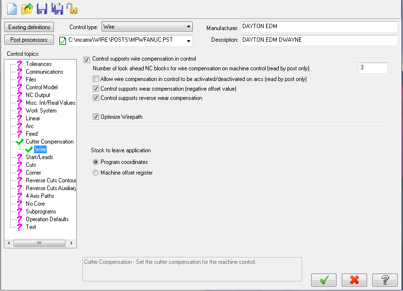
I actual looked into this and I don't have a compensation type : 5 choices unless I am missing something...See attachment: for Control Type: Mill, Router, Lathe, Wire, Mill/Turn. No Compensation type drop down and COMP direction drop down...
-
Good. As being new to this, the final confirmation is fine with me.
-
I know the internet is not always right but I found: G41 means the cutter stays to the left of the programmed path. G42 means the cutter stays to the right of the programmed path. If this is true with WEDM as well, is it not that important knowing the tolerance is pretty small so I should still get my .5 dia hole within or am I losing my case?? I know for a tool(mill) it might be more relevant(left, right)...
-
Attached is my MC file and below is the code from the file. % O0001(01B _HOLE) (DATE=DD-MM-YY - 19-09-13 TIME=HH:MM - 16:01) (MCX FILE - Y:\PB\MASTERCAM\REFERENCE\01A_HOLE.MCX) (NC FILE - Y:\PB\MASTERCAM\REFERENCE\01B _HOLE.NC) N100 G0 G20 G90 N110 G92 X0. Y0. I1. J0. N120 G0 X0. Y0. N130 M60 N140 M35 N150 M81 N160 S101 D1 N170 G41 G1 X.32322 Y-.32322 N180 G2 X.5 Y-.25 I.17678 J-.17678 N190 X.75 Y-.5 J-.25 N200 X.5 Y-.75 I-.25 N210 X.25 Y-.5 J.25 N220 X.32322 Y-.32322 I.25 N230 G40 G1 X0. Y0. N240 M50 N250 M30 % My concern is I been using MC for about less than a week along with help from Youtube/PDFs Tutorials. Is this part ready to be made(hole cutout) on a WEDM? If there any concerns beyond that let me know so I can better myself from this point foward? We use a : "Mitsubishi 1990: HA Series" http://www.mitsubish...58&Itemid=1158. Hope soon I can be importing CAD models and setting them up properly for machining with MC. 01B_HOLE.MCX
-
Thanks. I now understand alot more how that taper area works within the wirepath/contour parameters.
-
When I select the tool path and select PLAY, the Wire Edm runs the path I choose. There is a set distance between the top when the wire comes and then the bottom where the wire goes. Is there an option to increase/decrase this distance between so the tool won't drive into the part it is cutting. In reality you do raise and lower the tool to fit in the piece of but in Mastercam I want to know.
-
any ideas. Otherwise I will keep at looking...
-
I have a 1" from top to bottom of the tool that uses the wire. Can you increase and descrease this value so I can fit larger pieces inside or is it pre-detemrined on the piece I insert into mastercam already?
-
Hey again, I think I got some head way with this.Anyone want ot check out my update! I did not do a taper hole yet as I think I am not ready and then next I will do a straight to taper transition. Baby steps..... Let me know if eveything looks suitable or if you would do it differently? JBELLE7435-01.MCX
-
right now the bottom of the WEDM tool is inside the bottom of my part and the top ismuch higher that the part itself
-
Can you send me the solution file so I can see and understand how you got there. I know how to set up chains and get to the cutting stage but I know I am doing it wrong and need some direction.
-
I am getting some headway with this. Would I rather use contour or 4-Axis. with the 1° taper occuring in the middle of my piece ?
-
I got my thread points in there! Now where do I break the geometry? The transition edge between the straight 3/16 and the 1° taper ??