


MetalSlinger5
-
Posts
74 -
Joined
-
Last visited
Content Type
Profiles
Forums
Downloads
Store
eMastercam Wiki
Blogs
Gallery
Events
Posts posted by MetalSlinger5
-
-
10 minutes ago, crazy^millman said:
Need to make the nut part of the tool and not the holder. All holders are built with the understanding to stop at the top of the tool and not go below them.
totally understand but I cant seem to get any part of the geo under the "cutting" portion to be "non-cutting"
-
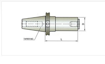
Is there a way to build a assembly for a slitting saw (not on an arbor) where the semi-flush nut that is holding the saw to the holder is non cutting geometry?
I have the holder built (without the nut) and the saw built, when I put the together, I cannot figure out how to have the nut under the saw as non cutting geometry.
any help is much appreciated
-
first time I have had this issue....
MCAM2022
machine: Haas UMC1000ss
toolpath: 2D high speed (equal scallop) with collision checking, tilt to avoid gouge is on.
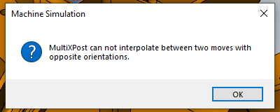
when the the tool (table) tilts to avoid, the table is rotating as well to avoid, at this transition, the tool is gouging the part. I have tried different things to fix to no avail.
I am reworking at bonding fixture from a outsourced company and am trying just to remove about .005" from multiple surfaces from this fixture.
thank you for any insight
-
after a little digging I found this at mastercam.com help center, but not sure exactly how to execute...
-
10 minutes ago, crazy^millman said:
Send email to the mothership attn Ruth and you should get the help you need.
sorry for being naive....mothership?
-
HSS drills will work in a pinch, carbide is preferred, diamond coated dreamers are best for drilling. I would try to helical bore holes in carbon fiber making sure to support the material around the holes for best results. there will more than likely be some delamination however you produce the hole, keeping it to a minimum is the goal. Use a solid carbide multi flute c-sink tool on the backside of hole to clean any delamination. good luck,
P.S. use plenty of air on the tool
-
 1
1
-
-
I have pretty much dialed in our setup sheets the way I like to see them for the shop floor, only thing I cannot figure out is why it will not transfer manual operations from MC2022 toolpaths to the setup sheet. I sometimes put operator notes to tell guys to move clamps or whatever, the NC code shows the comments, the setup sheet does not. Any of you gurus know what I am missing. Thanks
-
this one has me stumped....
I am building a slitting saw arbor/holder in MC2022 tool manager, this issue I am stuck on is the nut for the slitting saw. I can build the holder but how do I handle the nut that holds the saw by the ID? I could build in the saw and the nut, but that would cause a problem during verify, MC & Vericut would consider the saw as part of the holder and cause a "collision"
only other option I see would to leave the nut out of the equation and attach the saw as an assembly, but this option will eliminate the nut, thus not representing the actual tool in MC 7 Vericut.
-
thank you
-
MC2022 setup sheet question.
when using MC2021 and creating setup sheets, the image it captured from the screen would show up in color on the setup sheet, updating to MC2022, with all the same settings, the image captured show on the setup sheet black & white. I have looked at as many settings that I can think of, anyone have a solution for this or experiencing the same?
-
1 hour ago, crazy^millman said:
Look to the selection toolbar sometimes the solid becomes unselected in that selection bar. Just click it back and then you can re pick the solid and solid faces.

That is it! thank you!
-
1
-
-
is this a bug?
MC2021 latest release
Randomly solids become un-selectable when using the Analyze Dynamic function. I have to save and restart MC to be able to use this function, what is the deal?
-
I am going to build a holder library for every Techniks holder in our 2 machine shops, I have every .stp file from Techniks for every holder that they make and will pick and choose what we are already using and add as we purchase more. Here is my question for the guys that program not only for yourself and your shop, and the machinist on the floor, how do you like to see the information given to the machinist and operators on a setup sheet or however you present setup info?
1. As described on the actual holders: SYIC 22915-4.72RR
2. as described on the websites: 22915-2.5-CAT40xSLN3_8_-2-1_2_
3. In more common terms: 1/4" solid endmill holder 3" gauge length
4. some other way
I am leaning as described on the holder so there is no confusion on what holder to use.
-
1
-
-
Never seen this before when trying to use the toolpath verify....
MC2020
5 axis - G83 - Peck drill toolpath
-
seems like no matter what I do in the mastercam toolpath parameters, when I drill multi-axis holes on the Haas UMC machine, after each hole the machines G53 Z0's before every hole (tilt & rotation move), this has to be a post issue, correct?
(SPOT HOLES FOR KNKDL1032J KEENSERT)
T14 M06 (1/2 X 90DEG SPOT DRILL, 1.5)
G54 G17
S1528 M03
B90. C-82.957
M10
M12
G254
X-2.4008 Y-.5802
G43 H#3026 Z6.0269
M8
G94
G98 G81 Z4.8034 R5.1268 F12.22
G80
Z6.0269
G255
G53 Z0.
G54
M13
B90. C-82.475
M12
G254
X-2.4227 Y.4113
G43 H#3026 Z6.0262
G98 G81 X-2.4227 Y.4113 Z4.8026 R5.1261 F12.22
G80
Z6.0262
G255
G53 Z0.
G54
M13
B90. C-78.596
M12
G254
X-2.5393 Y5.5522
G43 H#3026 Z6.2507
G98 G81 X-2.5393 Y5.5522 Z5.0272 R5.3506 F12.22
G80
Z6.2507
G255
G53 Z0.
G54
M13
B90. C-69.129
M12
G254
X-2.3771 Y9.6105
G43 H#3026 Z7.5914
G98 G81 X-2.3771 Y9.6105 Z6.3679 R6.6913 F12.22
G80
Z7.5914
G255
G53 Z0.
G54
M13
B90. C69.129
M12
G254so on and so forth??
-
14 hours ago, gcode said:
you have the
"Only display associative geometry " button in the toolpath manager selected
and that solid is not associative to the toolpath you selected
ty ty ty, i thought i was losing my mind, this was it....
-
loosing it here....can someone explain to me why the visibility of a level would disappear visually when i select a toolpath in my toolpath tree?
-
first time creating a metric thread with a multi flute thread mill, help...
should I put in english dimensions for the cutter?
should I put english numbers in the cut parameters?
am I overthinking this?
-
thank you guys for your input and information, much appreciated.
-
4 minutes ago, Chally72 said:
Hi MetalSlinger,
The short answer is you're free to use whatever toolplane you want if you're using a rest stock model, but plane definition for stock models can be tricky if you're moving toolplanes around and don't understand what's happening to the stock model orientation in the background. If you can upload a file, we could step through how to set it up best for your particular example.
I was not using a rest stock model, I was just selecting the toolpaths from previous operations. Is it better to create a stock model up to that point and use it for rest milling?
-
not sure if I can explain this properly, but here goes..
when using any of the 3D or multiaxis toolpaths, and you want to use the stock/rest feature in the parameters, does the toolpaths that you want to use have to be in the same plane as the current toolpath you are creating?
Does not seem to work to me if the previous toolpath, for example, is tilted 25 deg. the toolpath that I am creating basically ignores the selection in the parameters...
-
2 hours ago, 5th Axis CGI said:
Varco Reports is what we use.
I am in contact with them, haven't heard back yet
-
3 hours ago, So not a Guru said:
I haven't shifted to 2020 yet, but I can share my 2019 sheet files & you should be able to migrate them.
This would be awesome! ty
-
Anyone willing to share an active report/ setup sheet file that you have found well for conveying setup info to the shop floor?
levels question
in Industrial Forum
Posted
Is there a way to set levels, so when mastercam opens a "new" file, that lets say the first 5 levels are named already by default?