


Frunple
-
Posts
9 -
Joined
-
Last visited
Content Type
Profiles
Forums
Downloads
Store
eMastercam Wiki
Blogs
Gallery
Events
Posts posted by Frunple
-
-
Might be a bug.
Turns out it works fine when drawn in metric. Comes out tiny when drawn in imperial.
-
Trying to save some files as STL and a 4" x 5" piece saves as 3mm x 4mm...am I missing a setting?
-
Actually I figured it out. Looks like Mastercam will do just fine for what I need!
-
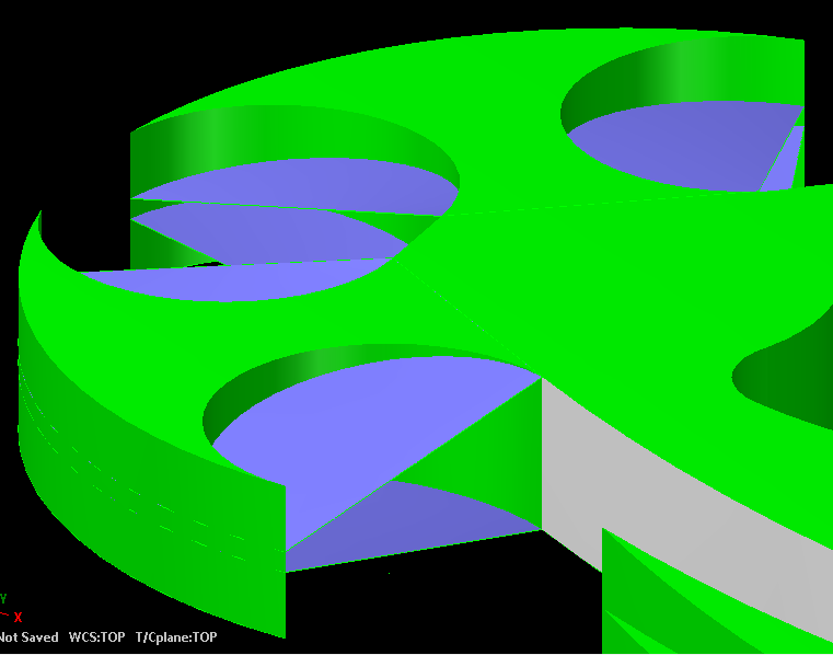
Today I made the whole thing out of an extruded solid.
In the attached, the green is the solid, the purple is the surface I want to be the top and bottoms.
Is there a way to "cut" away the part of the solid that are "outside" of the surfaces?
I tried the solid/trim but that didn't work. Any other commands to do this?

-
I went about it another way. Not the exact way I was looking for it but I think it'll do.
I'd be interested to see what you come up with though.

-
To create the top surface you will need to create a chain to revolve and than trim to surface. But first you need to look at the the sharp corner, the way it is drawn the two arcs cross over each other. That will cause you a lot of headaches trying to create the top surface.
Can you explain the "chain to revolve"?
Actually, they don't cross over, they are on different z depths so it looks like they cross but they aren't.
Would there be an easier way to get the "knife edge" on this?? I was thinking of starting with an .75" extruded piece, and them trimming it to get the edges. Is that possible?
-
Welcome to the forum!
What do you mean by "surface one part"? Are you wanting to close your part with surfs or toolpath the surfs you already have?
I see already you'll want to flip the surf normals so they all match EDIT > CHANGE NORMAL.
Toggle Alt+S until your surfs look like a mesh. If you rotate your part around, you'll see that there is a grayish side to one side of each surf. Use the change normal function until the green sides all point out. This will save you headaches down the road.
If you are wanting to put a top and bottom surf on it, there is not a simple answer I can give right now. I'll play with it and see what works best.
Yes, a top and bottom.
Not sure why the surface direction would matter but ok, easy enough to change.
-
So I'm trying to teach myself Mastercam by using drawings that i've done with another program.
So far so good I guess but I can't figure out how to surface one part I've made.
I've attached it here. Can anyone shed some light on this?

Nesting ignore.
in Industrial Forum
Posted
When using Geometry nesting, entities get colored as either Profile (green), Hole (red), or Ignore (grey).
I have some holes that get colored grey. Why is this?? They should be red for holes. What does "ignore" mean in this situation? I'm assuming it's going to be ignored as a toolpath but it shouldn't be.