randommachinist
-
Posts
28 -
Joined
-
Last visited
Content Type
Profiles
Forums
Downloads
Store
eMastercam Wiki
Blogs
Gallery
Events
Everything posted by randommachinist
-
 Thanks for the illustration. I see what you mean now.
 -
Sorry I was out of the shop all weekend. Anyways, unfortunately I'm not allowed to share the file with anyone outside of work, or I would! What do you mean it would have 130o of engagement?
-
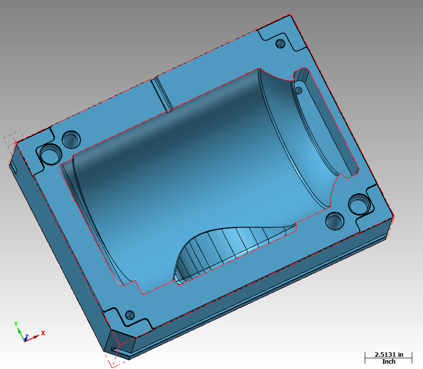
I have a question about machining a fillet with a tool that has a bigger radius than said fillet. For example, i'm working on a mold that has a couple fillets in some corners that are pretty tight (.125). The last toolpath i ran was with a 1/2'' ball endmill leaving ".015" stock to finish (optirest). My plan was to then run a finishing program (stock to leave "0.0") with the same endmill and clean up those fillets as much as possible. Here's my problem: I used the Surface/High Speed/ pencil toolpath and ran it in the machine. As soon as it came to the fillets, the endmill chattered like crazy. It looks as if there's a lot more than just ".015" stock to clean up. Why is that? Did mastercam ignore the fillets and not bring them down to the correct size because i'm using a tool with a larger radius than my fillets?
-
Stepdown To Leave For Finish
randommachinist replied to randommachinist's topic in Machining, Tools, Cutting & Probing
Alright. thanks! i'll give that a shot. -
Hey guys, I'm currently cutting out basically a 4 inch cavity. First i'm going in with a 1.000 indexable end mill and hogging out a bunch of material. Then coming in with a .500 endmill to clean up some fillets and corners. Lastly, i'll finish it up with a 1/2 ball endmill. My question is what kind of stepdowns should i use when i come in with the .500 endmill? I'm planning on leaving .015 stock. I'm just worried if i leave too big of stepdowns from the previous toolpath, it'll be too much stock to finish with. So does anybody have some good recommendations or a general rule of thumb to follow?
-
Best Finishing Toolpath for Cavity
randommachinist replied to randommachinist's topic in Industrial Forum
You're right, pencil unlimited looks great! is there some sort of leftover toolpath that i could use to go back and clean up the fillets though after i use my big primary finish tool? that way i don't have to start over with the pencil toolpath and run the hole thing from start to finish just to get to desired fillet with the correct endmill. -
Best Finishing Toolpath for Cavity
randommachinist replied to randommachinist's topic in Industrial Forum
Thanks guys for the help! I used scallop as one of you suggested, and I think the toolpath is what i'm looking for (I was having some issues with flowline). But also worried about the pock marks it might leave. So I was thinking of using a ball endmill that was bigger than my fillets for finishing, and then coming back to them with a pencil toolpath with the correct size endmill. Hoping to clean up those pock marks. You guys think that would work? or is there a better way? -
Hey guys, looking for any suggestions for a good finishing toolpath for this cavity. Planning on using optiarea for roughing, but not quite sure which path would work the best for a decent looking finish. I'm thinking surface finish contour or waterline are my best options. Any advice is much appreciated!
-
-
Hey guys, I know I posted a similar thread a couple days ago. But I'm really stuck on this and am desperate for some help. If anyone can take a look at this file and get a radius to go around the top edge of these letters that would be a huge help! Keep getting errors and don't know what to do! Alfa Romeo Email.mcx-8
-
How did you remove the lines on the solid?
-
Thanks, that would be great! let me know when you send it so I know if I got it or not.
-
Got a question for jlw, following your instructions, when creating the silhouette boundary I'm still having issues getting rid of all the line segments in the solid. I'm not sure if this is how you were getting rid of them or not, or is there another way around this?
-
Thanks guys for all the help! Really appreciate the input! I see what everyone is talking about and will have to try your suggestions when i get back to the computer.
-
Heres the File. I'm trying to put a 3/64 radius around everything Alfo Romeo Tail Light Radius Programs.mcx-8
-
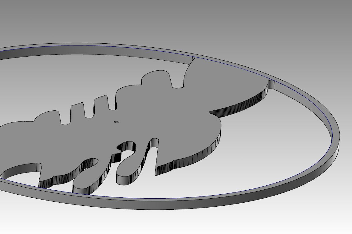
Hey guys, got a question hopefully someone can answer. Anyways, I attached a picture of the project I'm working on. Basically I have some letters that I've cut out and I'm trying to put a radius on the top edge of all the letters and around the outer perimeter. Ive been trying to use constant radius fillet or variable radius fillet and have had little luck. I've gotten an error every time I try to fillet anything. Does anyone have suggestions on how I can get a radius on these letters?
-
is there anyway to turn the STL file saved from verify into a solid with just the mastercam software?
-
Yeah I've tried toggling the stock model on and off and still no luck. I'll try saving it in verify and see what happens. Thanks
-
Thank! I see what you're talking about. I selected my previous toolpaths to compute the stock model from, but when I regen it, it doesn't show the stock model. Any Ideas? Is there also a way to turn that stock model into a solid so I can create the top radius around the lettering on it?
-
Hey guys, working with x8 here and this is my issue. Basically I'm cutting out some lettering and have a couple tight radius' in there. A few .030 and .015. Anyways, I roughed around the contours of the lettering with a .093 ball endmill, but of course its going to leave material where those tight radius' are. So I was wondering if there's anyway I can create a stock model or solid based off of what my .093 ball endmill machined. Because I may just go back and change those radius' so that my current cutter can hit them instead of ordering new cutters. However, I'm afraid that if I start changing my geometry I'm worried that it wont line up the lettering I already have cut out. Cause I also have to go back and radius the top edges of my letters. So everything has to line up correctly. Does anyone have any suggestions?
-
Need help matchin text to arc
randommachinist replied to randommachinist's topic in Industrial Forum
Wow, thanks for all the quick responses guys! Myth Project knows exactly what I'm trying to do. I'm going to try your suggestion when I get the time and see if that works! It just seems like I was messing around with xform roll quite a bit yesterday and still was getting what I wanted. Maybe I was just doing it wrong. -
The issue is this, I imported a logo off the internet using the rast2vec application in x8. So now I have a bunch of arcs and lines for the text, which I want to engrave into a part I'm doing. The problem is that I want the text to match to match a pretty large arc to give it a slight bend in the middle. I just don't know how to get all these lines and arcs to match up to the radius I drew. Anybody got any input on how to do this?
-
Hey guys, mastercam newbie here and need a little help. Basically I'm working on a project that has me cutting out some letters into an aluminum bezel for a car emblem. I got the text online and used the Rast2Vec application to create all my arcs and lines. however, they were pretty choppy and had to break all the lines into individual segments and play around with them to get them somewhat smooth. Anyways, I extruded them into a solid and want to put a radius around all the edges of the text. but when I extrude, I get hundreds of vertical lines where each line segment is in the text. Its extremely annoying when it comes to chaining the solid for the radius toolpath. Does anyone have suggestions on what to do to fix this? I tried joining the entities together but I still get a bunch of lines in my solid when I extrude. Also working with x8 here.
-
I ended up using Surface Finish Contour. Worked pretty good.
-
Hey guys, I have a little dilemma. Basically, I have a cylindrical part with an OD of around 7 inches. Then I have an offset hole that's around 4 inches that starts at the top of the part and then exits out the side of the cylinder, creating kind of an elbow. I have about .100 that I need to surface off in order to clean up my elbow. I can bore In from the top and side of the hole. But, that still leaves a gray area where the elbow makes that 90 degree turn. However, I have a coromill that's basically like a inserted disk that I plan on using to reach those areas. Does anyone have any suggestions to what kind of tool paths I would use to accomplish this? I noticed that whenever I try to use a pocketing tool path on my elbow, I get a "Warning-the boundary does not lie in the construction plane" error. I don't know what this means. I'm new to Mastercam and know very little. Any input is appreciated. thank!