


NiCu2829
-
Posts
24 -
Joined
-
Last visited
Content Type
Profiles
Forums
Downloads
Store
eMastercam Wiki
Blogs
Gallery
Events
Posts posted by NiCu2829
-
-
5 hours ago, David Colin said:
Good day David. Thank you for your support and thoroughness! I was able to get it to work on Saturday. I made some considerable changes. Here's the code, please feel free to critique. Thanks again for all your help!
#522=12.249(KEY CUTTER TOOL RADIUS)
#523=12.7(ACTUAL PART RADIUS)
#524=#523-#522(PROGRAMMED RADIUS FOR KEY CUTTER)
#527=15(# OF REPEATS FOR KEY CUTTER)
#528=16.36(G50V SHIFT AMOUNT)
#529=4.83(KEY CUTTER THICKNESS)
#530=16.36(TOTAL MATERIAL REMOVED)
#531=#530/#527(DEPTH PER PASS)
#544=21.946(PART DIAMETER)
#545=[#544+[#522*2]](EDGE OF TOOL ON OD)(KEY CUTTER)
(TOOL PROJECTION= 19.60MM-TO NUT)
(DIA= 6.28)
(*R VALUE ON OFFSET SCREEN=0*)
G40G97G98
M5
M80S3=87
T0700
M18C0
G50W-15.
G50V#528
G0X#814+2.5Y-[#545+4.]Z[14.986-#524]T07
G0X-#529
G19
M98H100L#527
G50V#528
G0Y-[#545+4.]Z[14.986-#524]
G0C45.
M98H100L#527
G50V#528
G0Y-[#545+4.]Z[14.986-#524]
G0C90.
M98H100L#527
G50V#528
G0Y-[#545+4.]Z[14.986-#524]
G0C135.
M98H100L#527
G50V#528
G0Y-[#545+4.]Z[14.986-#524]
G0C180.
M98H100L#527
G50V#528
G0Y-[#545+4.]Z[14.986-#524]
G0X#814+2.5
G18
G50V-#528
G50W15.
G0Z-4.5
G0Z-4.5T0
M82
M20
M5
G18G99
M1M2
M99N100
G50V-#531
G1Y-30.988F1000.
G3Y-30.988Z[14.986+#524]R#524
G1Y-[30.988+4.]
G0Z[14.986-#524]
M99
-
1 minute ago, David Colin said:
Yes i saw that. I left my CAM desk until monday but if toolpath is correct you should be pretty close!
You just need to adjust first pass entry point.
G0X#814+2.5Y-[#542+4.]I guess you should calculate this "+4" safety value and put it in a variable (using part diameter #544 and cutter radius #522).
WIll do. Time to make it happen.
Thanks again for all the support!
Have a great weekend!
-
1 hour ago, David Colin said:
Mmmh...
could you try to change:
#542=2*[[#544/2]-#541+#523] (FIRST PASS)It corrected the Y axis value at the bottom of the arc. It's currently Y-30.086 which is correct, but the start position(FIRST PASS) is now coming down on top of the part(to close to centerline).
-
8 minutes ago, David Colin said:
Mmmh...
could you try to change:
#542=2*[[#544/2]-#541+#523] (FIRST PASS)I'll certainly try it. I'll keep you posted.
-
1 hour ago, David Colin said:
I would leave #540 as a radius value as it's used for calculations
but I would change in initialization :
#542=2*[[#544/2]-#541+#523+#522]and in sub:
#543=#543-2*#541(RECALCULATE DEPTH)The results of the test are as follows:
The absolute Y value at the bottom of the arc(max engagement) stayed the same regardless of #527 value, which is what I'm looking for.
The current issue is the absolute Y axis value at the bottom of the arc=Y-54.584, it should be Y-30.086. It's to far away from centerline.
Information I've gathered:
54.584-30.086=24.498
24.498-25.4(#523*2=25.4) = .902(#524*2=.902)
Currently #542=55.486(54.584(absolute Y axis value at bottom of arc) + .902 = 55.486)
It's really close! I can't seem to see what's incorrect. Thanks again for your time!
-
24 minutes ago, David Colin said:
I would leave #540 as a radius value as it's used for calculations
but I would change in initialization :
#542=2*[[#544/2]-#541+#523+#522]and in sub:
#543=#543-2*#541(RECALCULATE DEPTH)Thank you so much! A second set of eyes/second opinion is helpful. I'll test it now.
-
4 minutes ago, David Colin said:
Just in case you didn't see it (as we post at same time). I post an updated file above.
Yes sir, I saw it. Thank you for the assistance. I posted a question regarding your latest post.
-
4 minutes ago, David Colin said:
I found glitches testing it...
Try this one instead: 311-MOD-2.txt
Here are modifications:
#540=15.494(DISTANCE FROM CENTERLINE OF PART TO CENTER OF ARC)
#544=21.946 (PART DIAMETER)
#541=[[#544/2]-#540+#523]/#527(DEPTH PER PASS)
#542=[#544/2]-#541+#523+#522 (FIRST PASS)
The machine is a Citizen L32. The Y axis is diametrical so if I G0 Y-21.946 (part diameter) it physically moves the tool half that amount (10.973). With that being said, should #540=15.494 or [15.494*2] ?
-
4 hours ago, David Colin said:
Hi,
Try changing :
#540=[15.494*2]-[#523*2](DISTANCE FROM CENTERLINE OF PART TO BOTTOM OF ARC)
#541=[21.946-#540]/#527(DEPTH PER PASS)
with:
#540=[15.494*2](DISTANCE FROM CENTERLINE OF PART TO CENTER OF ARC) #541=[[21.946-#540]/2]/#527(DEPTH PER PASS)I'll try it. Thank you for your time!
-
Attached is the latest edition of the program. It's still not working correctly. When I change #527 the absolute Y value changes. I want the toolpath to finish at the same Y axis location regardless of #527. The only thing I want to change dependent upon #527 is the DOC(depth of cut).
(PROGRAM IS IN METRIC)
$1
#522=12.249(KEY CUTTER TOOL RADIUS)
#523=12.7(ACTUAL PART RADIUS FOR KEY CUTTER)
#524=#523-#522(PROGRAMMED RADIUS FOR KEY CUTTER)
#527=10(# OF REPEATS FOR KEY CUTTER)
#528=8.179(16.358)(G50V SHIFT AMOUNT)
#529=4.83(4.699)(KEY CUTTER THICKNESS)
#540=[15.494*2]-[#523*2](DISTANCE FROM CENTERLINE OF PART TO BOTTOM OF ARC)
#541=[21.946-#540]/#527(DEPTH PER PASS)
#542=[[15.494*2]+[#541*#527]](FIRST PASS)
#543=#542
(AB TOOLS-KEY CUTTER)
(CARBIDE TOOL)
(6 FLUTES)
(DWG # )
(TOOL PROJECTION= 19.60MM-TO NUT)
(DIA= 6.28)
(*R VALUE ON OFFSET SCREEN=0*)
(#522=KEY CUTTER TOOL RADIUS)
(#523=ACTUAL PART RADIUS FOR KEY CUTTER)
(#524=PROGRAMMED RADIUS FOR KEY CUTTER)
(#527=# OF REPEATS)
(#528=G50V SHIFT AMOUNT)
(#529=KEY CUTTER THICKNESS)
(#540=DISTANCE FROM CENTERLINE OF PART TO BOTTOM OF ARC)
(#541=DEPTH PER PASS)
(#542=FIRST PASS)
(#543=#542)
(G10L10P7X0Y0Z15.Q0R0.)(R#522)
(G11)
/MB7
G40G97G98
M5
M80S3=871(=220SFM @ .9645" DIAMETER)
T0700
M18C0
G50W-15.
G50V#528
G0X#814+2.5Y-[#542+4.]Z[14.986-#524]T07
G0X-#529
G19
#543=#542
M98H100L#527
G0Y-[#542+4.]Z[14.986-#524]
G0C45.
#543=#542
M98H100L#527
G0Y-[#542+4.]Z[14.986-#524]
G0C90.
#543=#542
M98H100L#527
G0Y-[#542+4.]Z[14.986-#524]
G0C135.
#543=#542
M98H100L#527
G0Y-[#542+4.]Z[14.986-#524]
G0C180.
#543=#542
M98H100L#527
G0Y-[#542+4.]Z[14.986-#524]
G0X#814+2.5
G18
G50V-#528
G50W15.
(G50 Y0.)
G0Z-4.5
G0Z-4.5T0
M82
M20
M5
G18G99
/MB7
M1
M2
M99N100
G1Y-#543F132.74(FEED/MINUTE)(=.001")
G3Y-#543Z[14.986+#524]R#524
G1Y-[#543+4.]
G0Z[14.986-#524]
#543=#543-#541(RECALCULATE DEPTH)
M99
-
15 minutes ago, SlaveCam said:
I always put precondition checking in my macro programs to avoid infinite loops or too large stepovers and other nasty things, when one mistypes a digit.
Would you provide an example. This is relatively new to me. Thank you for your time!
-
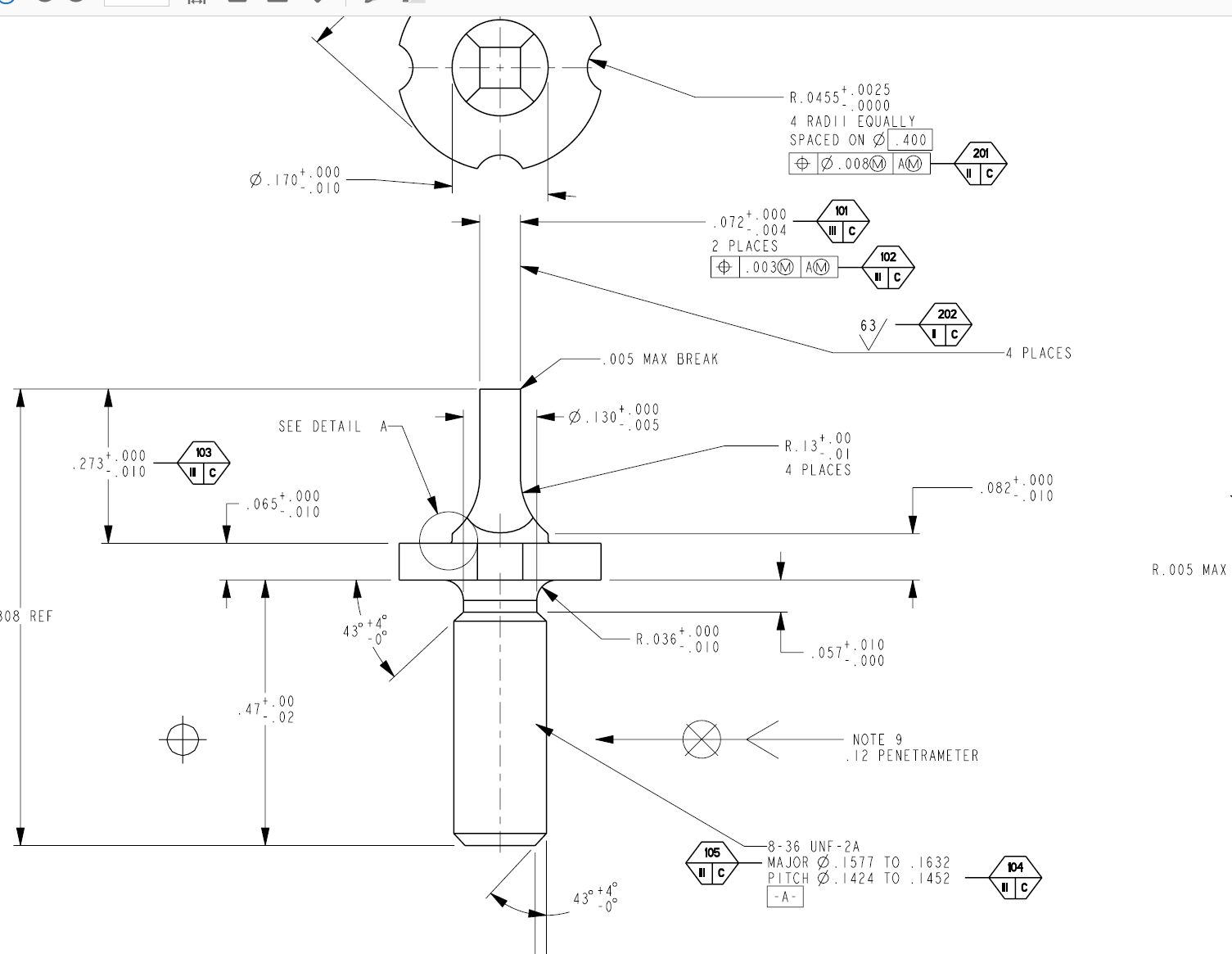
I've attached the blueprint of the part to be made and my code to machine the 5 slots in the OD. My goal is to have a program that regardless of the tool diameter, programmed radius or # of passes/DOC can be changed with relative ease. I'd like to make #527 passes where each pass is #528/#527 deep (the actual DOC is [#528/#527]/2 because the Y axis is diametrical).
I've never used variables to this extent so I'm hoping y'all will look it over and critique my code.
In the program I accounted for the key cutter tool radius when I programmed the tool path, so the R value on the offset screen=0.
I'm cutting on the minus(-) side of Y0.
Thanks in advance!
-
I've attached the blueprint of the part to be made and my code to machine the 5 slots in the OD. My goal is to have a program that regardless of the tool diameter, programmed radius or # of passes/DOC can be changed with relative ease. I'd like to make #527 passes where each pass is #528/#527 deep (the actual DOC is [#528/#527]/2 because the Y axis is diametrical).I've never used variables to this extent so I'm hoping y'all will look it over and critique my code.In the program I accounted for the key cutter tool radius when I programmed the tool path, so the R value on the offset screen=0.I'm cutting on the minus(-) side of Y0.Thanks in advance!
-
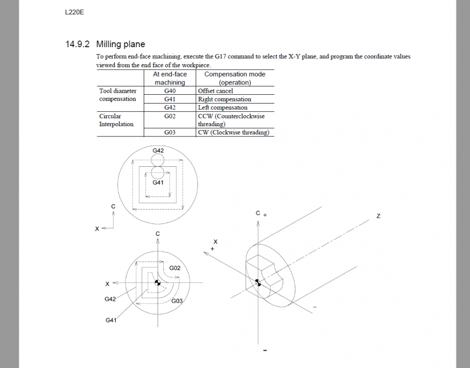
I'm currently not seeing the results I'd like with the G12.1. Attached is the current code (Citizen L20-Mitsubishi control) and the blueprint. The print is in inches but the program is in metric. I programmed the final part dimension + the radius of the tool (.125"), this way the R value on the offset screen is 0.
The issues are as follows, the final dimension is approximately .032" to big on the .072" +0./-.004" dimension(width across flats). I've programmed the X and C axis radially. I verified that the tool is centered (X0./Y0.) to the sub-spindle.
Also, there's no .127mm(.005") radius on the corners of the square.
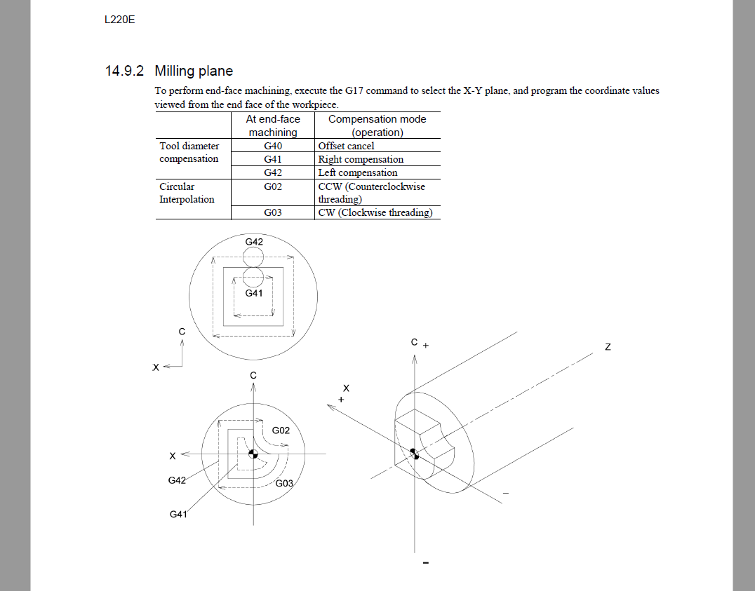
As the program reflects I'm using G41 and G2's. Per the attached picture captured from the Instruction Manual for the Citizen L20, I should be using G42 and G3's, which is correct? I'm wondering if this is why my part has no .127mm(.005") radius on the corners of the square?Thanks in advance for the support.

-
I'm currently not seeing the results I'd like with the G12.1. Attached is the current code (Citizen L20-Mitsubishi control) and the blueprint. The print is in inches but the program is in metric. I programmed the final part dimension + the radius of the tool (.125"), this way the R value on the offset screen is 0.
The issues are as follows, the final dimension is approximately .032" to big on the .072" +0./-.004" dimension(width across flats). I've programmed the X and C axis radially. I verified that the tool is centered (X0./Y0.) to the sub-spindle.
Also, there's no .127mm(.005") radius on the corners of the square.
As the program reflects I'm using G41 and G2's. Per the attached picture captured from the Instruction Manual for the Citizen L20, I should be using G42 and G3's, which is correct? I'm wondering if this is why my part has no .127mm(.005") radius on the corners of the square?Thanks in advance for the support.


-
You should call Doosan because your machine is not acting normally.
You'll want to check if M289 is on by default.
If it's not, you'll need to command M289 before the G84 canned cycle call.
Why do you want a 2 second dwell at the bottom of the tapped hole?
I've never done anything like that with rigid tapping.
I never use a dwell with tapping at all.
I'll give them a call. I've never put a dwell at the bottom of a tapped hole either. I was curious as to why someone would use that feature and I wanted to figure out why it wasn't working like it was supposed to. I got this number from their website 1-888-9Doosan(936-6726). Is this the best number to contact them or should I e-mail technical support? Thanks for all your help Tim.
Best regards,
Branden B.
-
 1
1
-
-
I appreciate the kind words but that's really not the case.
When it comes to Doosan, Bob Appleton at Doosan HQ is the best there is.
I recognize the name.
I tried the code today to no avail. The P address worked as it should but the spindle still unlocked once it read the M29. I had the M89 on the G84 line and the machine wouldn't continue on. I deleted the M89 and it would run but the spindle would unlock. I should also mention that if I type in M35 in MDI the spindle locks but when I put it in handle it unlocks. So I can not manually rotate the C axis in handle mode. Not sure why? I know that M89 is set in the parameters for clamping but I didn't check M289/M389?
Best regards,
Branden B.
-
Sure.
However, a rapid approach with all axes is something i avoid like the plague.
G00 G28 U0 V0
G00 G28 W0
Txx00
M01
T0909
M90
M35
G28 H0.
G0 G54 X5. C0. (Y0 isn't needed)
Z.25
M177
G97 S500 M29 P12
G99 (Explicit UPR Mode Call for Tapping with Pitch for Feedrate)
G84 Z-.5 R0. P2000 F.0625 M89
C180. P2000 M89
G80
Tim,
It's easy to see why people say you're the "best resource for these machines." THANK YOU.
Sincerely,
Branden
-
Your aren't positioning properly before calling the cycle.
You should be at your start point in XC and initial Z before calling the cycle.
It's poorly formatted code because you don't have an explicit Z initial position.
However, the fact you don't have an R word on the G84 is your problem.
You aren't telling it to retract properly.
The R-Word MUST be there.
The R-Word for drilling cycles is different in turning.
It is the incremental distance from the initial level to point R level.
If your initial position and R-Plane are the same, R0 is what you should have in your cycle.
If your initial position is Z1.0 and the R-Plane is at Z0.1, R-0.9 is what you should have in your cycle.
Will it work if my initial Z position is Z.25?
T0909
M90
M35
G28 H0.
G0 G54 X5. Y0. Z.25 C0.
M177
G97 S500 M29 P12
G84 Z-.5 R0. P2000 F.0625 M89
C180. P2000 M89
G80
I greatly appreciate the insight Tim.
Thanks,
Branden
-
You are probably still missing something.
Post your code so I can see what you have.
The P address is permissible but remember that it is a Dwell and the value is in milliseconds.
No decimal point.
T0909
M90
M35
G28 H0.
G0 G54 X5. Z.25 C0.
M177
G97 S500 M29 P12
G84 Z-.5 P2000 F.0625 M89
C180. M89
G80
Thanks,
Branden
-
You need to read your manual and properly format your code.
The P address on a Doosan indicates which spindle is active as in S1000 M03 P11 (Main Turning Spindle)
You need an M35 to tell the machine you are now using a live tool.
You need an M176 for Left-hand tapping and M177 for right-hand tapping.
M35 (Live Tooling Mode - Engage C-axis)
G28 H0.
G00 X50.0 C0.0 (Positioning the drill along the X and C axis)
M177 (Right-hand Tapping)
M29 S1000 P12 (Rigid Tap mode - P12 indicate Live Tool Spindle at 1000 RPM)
G84 Z-30.0 R-5.0 F1500 M89 (Tapping hole 1 Along Z Axis - G88 for X-Axis Tapping)
C90.0 M89 (Tapping hole 2)
C180.0 M89 (Tapping hole 3)
C270.0 M89 (Tapping hole 4)
G80 (Cancel the Tapping cycle)
M05 P12 (Stop Live Tool)
M34 (Return to Turning Spindle Mode)
Hello Tim,
First off thank you. I looked through the manual but missed the M177. I'll be sure to try it tomorrow, other than that our code looks the same. I understand the use of the P address in relation to the spindles meaning it can't be used on a G84 line?
Thanks again
Branden
-
Fanuc G84 Peck Rigid Tapping Cycle Format
G84 X_ Y_ Z_ R_ P_ Q_ F_ K_ ;
X Y – Hole position.
Z – Z-depth (feed to Z-depth starting from R plane).
R – Position of the R plane.
P – Dwell time at the bottom of the hole and at point R when a return is made.
Q – Depth of cut for each cutting feed (Peck depth).
F – The cutting feedrate.
K – Number of repeats (if required).
When I use a P command on my G84 line the spindle continues to rotate at the bottom of the hole, ruining the threads. I'm working on a Doosan Puma 2600SY lathe. Also when I use M29 (rigid tapping) w/ G84 it unlocks the spindle so I'm only able to use rigid tapping on center. Any thoughts or insight would be greatly appreciated.
Thanks - Branden
-
Your feed should be 2mm or .0787" not .05" for your tap using feed per rev. If you are worried about horsepower I would thread mill anything this large. As for peck tapping, add a Q.1 to your G84 line and it will do a .1 peck.
Fanuc G84 Peck Rigid Tapping Cycle Format
G84 X_ Y_ Z_ R_ P_ Q_ F_ K_ ;
X Y – Hole position.
Z – Z-depth (feed to Z-depth starting from R plane).
R – Position of the R plane.
P – Dwell time at the bottom of the hole and at point R when a return is made.
Q – Depth of cut for each cutting feed (Peck depth).
F – The cutting feedrate.
K – Number of repeats (if required).
As a general rule I wouldn't try re-running a tap, it usually doesn't end well.
When I use a P command on my G84 line the spindle continues to rotate at the bottom of the hole, ruining the threads. I'm working on a Doosan Puma 2600SY lathe. Also when I use M29 (rigid tapping) w/ G84 it unlocks the spindle so I'm only able to use rigid tapping on center. Any thoughts or insight would be greatly appreciated. Thanks.


Variable Programming - Critique My Code, Please
in Industrial Forum
Posted
Agreed. It's what made sense to me. Now I'm trying to add a finish pass so to speak. I'd like to leave a certain amount of material for the last pass regardless of the DOC of the previous passes. Any thoughts?