Matt@RFR
-
Posts
6 -
Joined
-
Last visited
Content Type
Profiles
Forums
Downloads
Store
eMastercam Wiki
Blogs
Gallery
Events
Everything posted by Matt@RFR
-
No dice for me at all, same results as I got in my first post. I didn't mention this, but I'm only making two of these so this is the solution I went with. Thanks everybody!
-
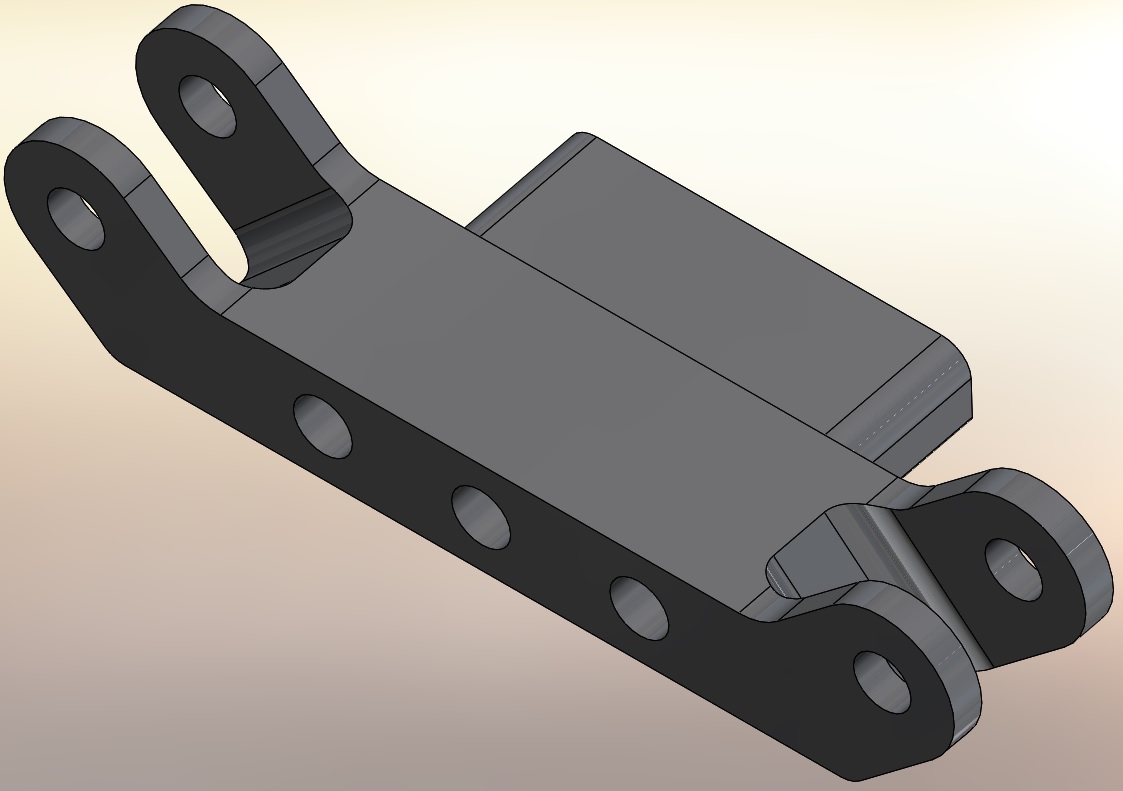
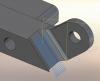
Sorry guys, I really struggled coming up with a decent thread title, hopefully what my puny brain puked out will work ok. MC4SW X9 Picture 1 is the part showing the two end slots with angled walls. This is the problem area. The two parallel walls are vertical. Picture 2 shows the best tool path I could put on it. It's a simple 3D contour finish, but I've tried all of the 3D finishing (and even 3D contour rough), but I just can't get it to work for me. I've also modeled plugs for those holes with no changes to the tool path. The first (top) pass on picture 2 shows what I need; The tool starts off the part and finishes all 3 walls of the slot. I just can't get MC to do that on all the rest of the passes. TIE ROD MOUNT.SLDPRT Anyone have an idea of how to get this to work?
-
X6 3D chamfering with Lollipop, help needed
Matt@RFR replied to Matt@RFR's topic in Industrial Forum
Got it! With all the messing around I had been doing, I inadvertantly moved my stock model down in Z .070" so nothing was making sense in verify. I have no idea how I did that, but now that it's fixed, things are working nicely. THANK YOU! -
X6 3D chamfering with Lollipop, help needed
Matt@RFR replied to Matt@RFR's topic in Industrial Forum
Ron, your method made perfect sense and taught me several things, so thank you very much for that. However, it's just not working. When I offset the surfaces, they will either twist or fold on to themselves. Failing to fix that, I used flowline curve on the good surfaces and used blended splines to connect the geometry I needed, but still end up with really funky shaped chamfers. I'm sure I can eventually get what I need by manipulating the geometry by trial and error, but as you can imagine this is adding a huge amount of time to an otherwise simple part. -
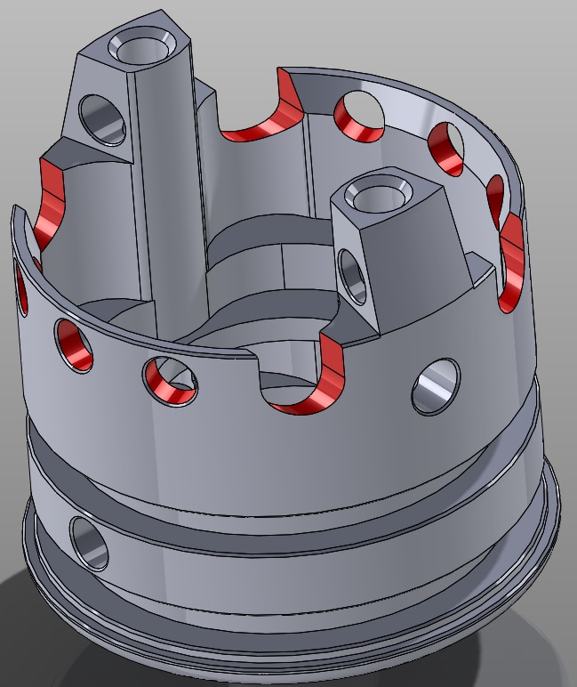
I've got a part that is driving me crazy trying to chamfer everything and am hoping you guys can help me with it. My .mcx file is attached. The features in red are what need to be chamfered, on the ID of the part only. Everything else is taken care of. .005" chamfers. I will be using an 1/8" lollipop for these features. I realize a regular ball would do it but I need the lollipop in another area so it will already be in the spindle. The customer estimates needing upwards of 500 / month of these parts, so cycle time is important. I have tried 3D chamfer, pencil, flowline, scallop and blend, both with and without chamfers on the solid, with absolutely no luck. Some came close but ended up looking just like I ran the cutter straight in to the hole, which I also tried. If anything came close to working, I always ended up with the chamfer being way too uneven around the features. I also tried all of the above toolpaths on a different plane to see if the vector made a difference, which it didn't. I would appreciate any help with this! I've been flogging it for a couple days now and just need to get it ready for production. BASE FINAL REV B.MCX-6