


Stephen
-
Posts
92 -
Joined
-
Last visited
Content Type
Profiles
Forums
Downloads
Store
eMastercam Wiki
Blogs
Gallery
Events
Posts posted by Stephen
-
-
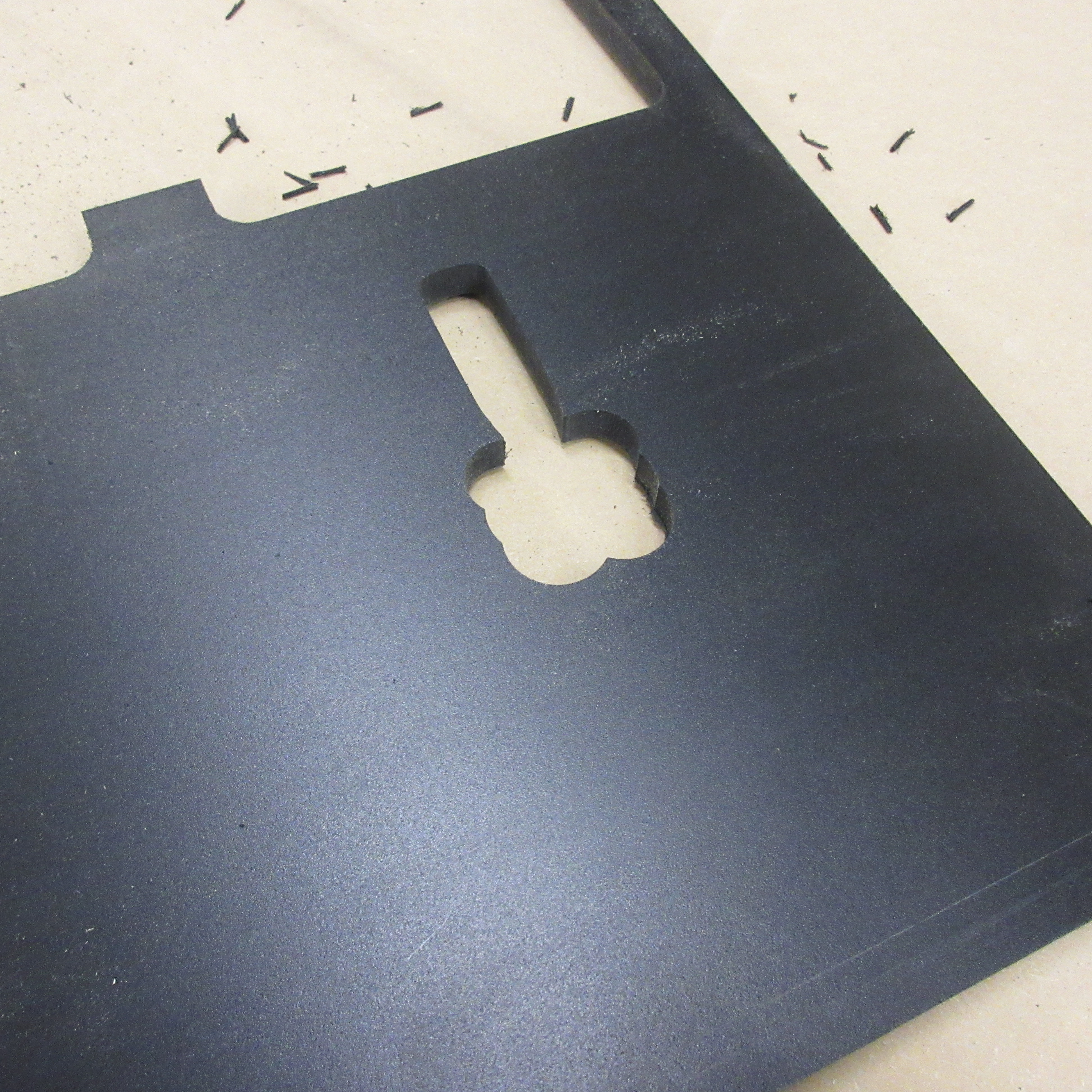
The engraving toolpath works. I had to draw extra geometry to create an outer boundary for the male part since it is outside of the square. This causes the tool to make an extra cut(outer boundary) where the is no material. It's not a very efficient toolpath, but it works. Is there a way to do this with a regular contour toolpath?
Steve
-
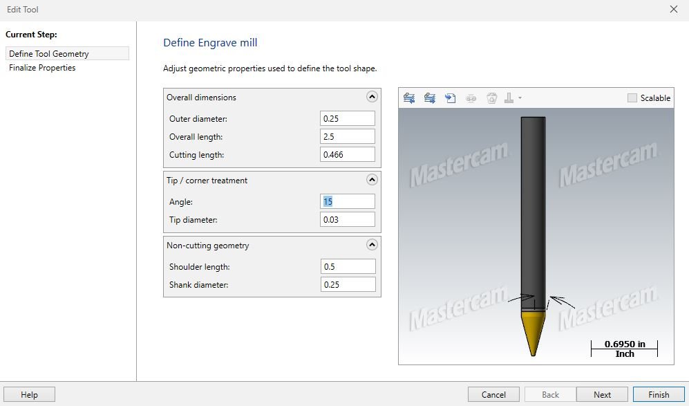
This is my tool:
-
Hello,
I'm sure this had been coved but I can't find it searching the forums. I creating a chess board that will have an .125" inlay depth for the 2 inch colored squares(.125 radius corners). I'm using an Onsrud 30 degree included angle cutter with a .03 flat tip. How do I get the cutter to follow the simple wireframe geometry for any given depth? I've defined the tool, but it always compensates from the cutter body diameter, not the tapered part of the tool.
Thanks for the help,
Steve
-
Jayson,
So you are saying this particular machine is already in the MC system and ready to go? If you could convey that to Chris at MCAMNW that would be appreciated.
Steve
-
 2
2
-
-
I think I have all the files now. Royal and Benz sent me the files I needed this morning. I will forward all of it to my MC reseller and hopefully that is all they need. Thanks again for all the expert help.
Steve
-
Nice fixture!
That link worked great. I found the radial and axial toolholder models. I emailed Benz for my other radial holder. I also emailed Royal for my collet holder. Are there any CAD libraries online for the basic BOT toolholders for round and square shanks? I was able to find my Kennametal tooling files online,
Steve
-
Millman- Thanks! I appreciate the help.
This has been a frustrating adventure. When I asked Selway for the files they said: Your MC reseller has the files or get them off the Haas website.
Where can I find the working holding files?
Steve
-
I'm confused as far as how to proceed. I paid for the simulation environment upgrade. My MC reseller ask me to gather the CAD models for my machine and the locators. They did not want to be responsible for them because of all the various configurations of my machine. What should be my next move?
Steve
-
I have the license. MasterCAM does not provide the machine specific CAD files.
Steve
-
Hello,
I'm working on getting the MasterCAM lathe simulation environment for a 2015 Haas ST-10Y lathe. The Haas website only has the most current CAD model with a sub-spindle available. I have a tailstock. They also do not have any locators. I have the 12 station hybrid (6 VDI / 6 BOT) with Eppinger(Preci-Flex) and Benz axial and radial holders. Does anyone have the files for this machine they could share or can point me in the right direction?
Thank you,
Steve
-
So after trying many tweaks only one worked. I changed the pocket roughing choices from parallel spiral to constant overlap spiral and it worked perfectly. Does this mean there is something wrong with the parallel spiral routine? Thanks for all of your suggestions.
On a different note, what do you recommend for settings on the arc filter/ tolerance tab? The router does not get up to the programmed feed because of all the splines, short arcs, and lines. Or is there another setting to speed things up?
Steve
-
BenK- Changing the control file did not make a difference.
Gcode- I checked my oldest files and they all use I &J for arcs.
Matthew- Is your backplot different than Gcodes?
I think I will completely redraw the outline in MC to make sure something was not corrupted from the Rhino geometry import.
Steve
-
Attached is the NC file.
-
Can I save it as something else? I thought instructors SIM was regular seat? This must be a change because it use to save as a .MCX without the E.
-
-
I have a real basic shape that is a 2D outline of a screwdriver traced in Rhino. It was imported to X9 as splines, lines, and arcs. In MC I added a finger tab(half circle on either side of the handle with a small blending fillet). This is a shadow board for a toolbox drawer. So I have a basic pocket tool-path with a .25 end mill and back-plot and verify come out perfect. Unfortunately, the router cuts way out of the boundaries by the finger tabs and ruins the part. I've converted the splines to lines and re-chained the geometry. The simulation looks great, but again the code is wrong. I have never had a problem with this machine or post. So is this a post problem or MC programming problem? How do I go about fixing this?
Thanks,
Steve
-
JLW- Thanks for the offer. I do need to get three bids.
Colin- Yes I'm specifying the setup and passing it off to purchasing.
Any suggestions for a base model from Dell to start with?
Steve
-
Hello,
I need to get about 15 computers for my schools computer lab. Specifying computers is not my forte. I would like dual 23" monitors and a desktop system. It needs to run MasterCAM, Solidworks, Rhino, and CorelDraw. Should I use a vendor like Dell or? I do need to have them in my possession by the end of this month due to end of year budget spending requirements.
Any help would be appreciated,
Steve
-
I finally figured it out. I renumbered my file to O8665 instead of O9665. NEVER name a file O9XXX for transferring USB files to the controller. I had no idea about this and it did not come up in my Haas training's or classes. I think it's tied to setting #23. Does anyone know more about this?
Steve
-
It's a .nc. If it was wrong I don't think it would open in the editor? I'll have to check the other files.
-
I can't transfer a USB file(MC) over to memory on my VF-2. I have renamed the file and I have plenty of room on the drive. Older files on my USB will still transfer. The weird part is I can select and open the problem file in the editor. Very frustrating! What am I missing?
-
What is the best code for the return to tool change position? My post outputs G28 U0 V0 W0. The V0 causes alarm 357 AUX AXIS DISABLED.
A plain G28 causes the return to get in the path of the tailstock.
The other problem is it normal on a new machine to not have the boring/drill tool holders(1" and 1.25") not be on the spindle centerline?
For example, some tool numbers will only dial-in using the Y axis offset. Other tools will dial in at Y0.
Thanks,
Steve
-
2
-
-
Thanks!
If I select keep both pieces the tool path won't refresh. It just stays "X" out with no errors. What would cause this? The other two options work fine.
-
I have the same problem, but where exactly is the stock update tab under the comment box? I'm not seeing it.
Tapered endmill cutter compensation
in Industrial Forum
Posted
Rekd,
The tip is blunted by .03. With the compensation off it drives the center of the tool on the geometry, not the edge of the tool.
Steve