Ucuellar2011
-
Posts
8 -
Joined
-
Last visited
Content Type
Profiles
Forums
Downloads
Store
eMastercam Wiki
Blogs
Gallery
Events
Everything posted by Ucuellar2011
-
Hello, I have used the information on this forum post ' https://www.emastercam.com/forums/topic/64263-max-min-depth/ " to add min max depth to several posts in the past. However this latest post that I have added it to has not gone so smoothly. I am mainly having an issue with the values being spit out i suspect the buffer is not receiving the correct value it always reports max @ z-99999. and min @ z99999. I think this is due to the pwrtt block being missing in my post, I added it to the post but had to remove the "$" symbol else i would get an error about duplicate labels. Any help getting this working would be greatly appreciated.
-
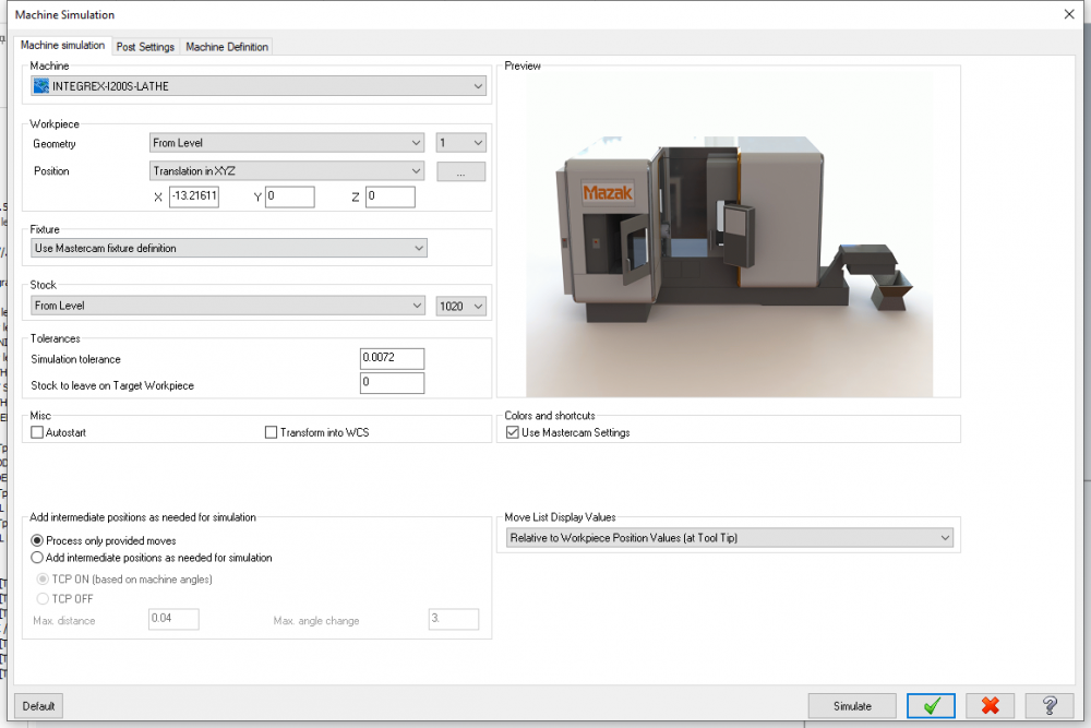
Machine Simulation - MASTERCAM 2019-2020
Ucuellar2011 replied to Ucuellar2011's topic in Machining, Tools, Cutting & Probing
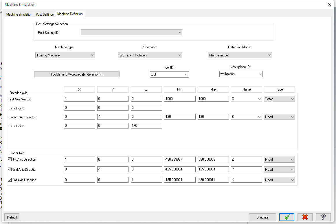
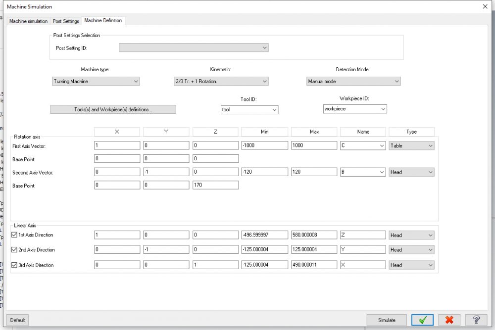
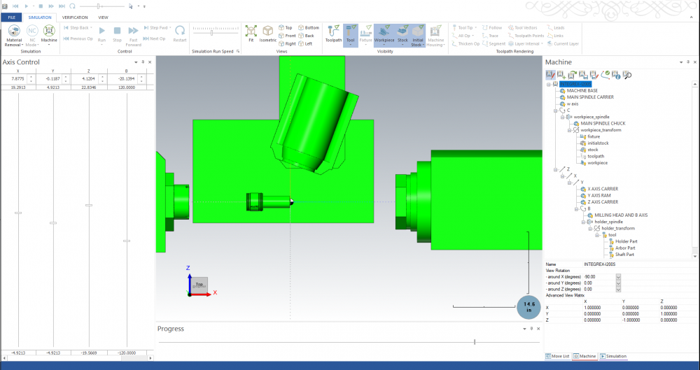
Back in the shop , yes you are correct about the B-axis. Also the post processor needs some adjusting. MACHINE BASE.stl DIMENSIONS.BMP fixture.stl INTEGREX-I200S-LATHE.xml MACHINE BASE.stl MAIN SPINDLE CARRIER.stl MAIN SPINDLE CHUCK.stl MAIN SPINDLE FACE PLATE.stl MAIN SPINDLE CARRIER.stl MAIN SPINDLE CHUCK.stl MAIN SPINDLE FACE PLATE.stl MILLING HEAD AND B AXIS.stl MILLING HEAD AND B AXIS.stl STL OF ALL THE COMPONENTS METRIC.stl SUB SPIDNLE CARRIER.stl SUB SPINDLE CHUCK.stl workpiece.stl X AXIS CARRIER.stl X AXIS CARRIER.stl Y AXIS RAM.stl Y AXIS RAM.stl Z AXIS CARRIER.stl Z AXIS CARRIER.stl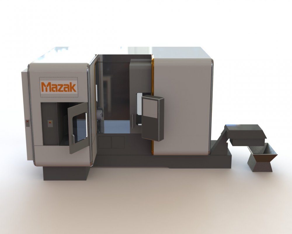


-
Machine Simulation - MASTERCAM 2019-2020
Ucuellar2011 replied to Ucuellar2011's topic in Machining, Tools, Cutting & Probing
It think world z should match machine z , its been a while. -
Machine Simulation - MASTERCAM 2019-2020
Ucuellar2011 replied to Ucuellar2011's topic in Machining, Tools, Cutting & Probing
Hi I just saw your PM, id be more than willing to share, I will be out of the shop for a few days. But I can send you my sim file and set yours the same. Try re assembling it but dont add the c axis until the end. Before you import components right click it and add a rotation right away. I think it should revolve around the x axis. But I think i assembled the machine on front view in mastercam and had the issue with the tool coming in 90 deg off. So I did an xform and got it to top plane. Than saved the stl's in this orientation. And the first thing you do in the mach SIM is rotate it back to what would be the front view. -
Hello, I have been using stock models on 2018 and 2019 with little to no hiccup. However I am on 2020 now , I have done two parts so far and both Ive had different issues. On the first, the stock model never renders on screen unless i use stock compare, it will generate and export just fine. On the second file the model renders on the screen however I cant seem to get it to un-render. In other words on 2019, when you green check box on the tree your stock model - it appears in the view, and goes away if you select any other op. i have it permanently which is displayed. Am I missing something?
-
Machine Simulation - MASTERCAM 2019-2020
Ucuellar2011 replied to Ucuellar2011's topic in Machining, Tools, Cutting & Probing
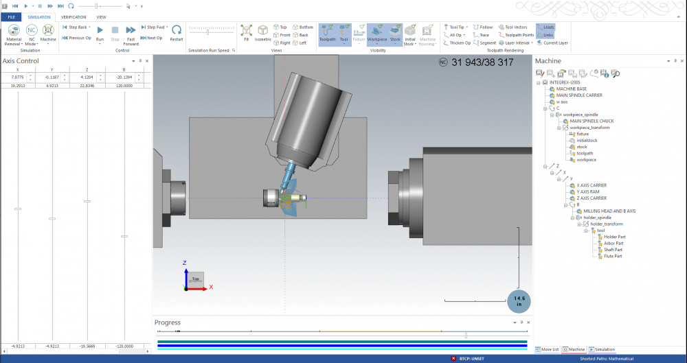
I played around with it some more, I got it to work! it was actually very simple, i started assembling the machine all over when i realized the first bullet has a machine shift, i rotated the whole machine 90 deg to coincide with top plane, now it works like a champ, both turning and milling tools run perfect now!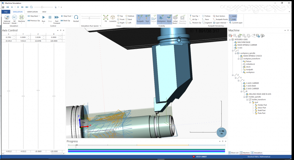

-
Machine Simulation - MASTERCAM 2019-2020
Ucuellar2011 replied to Ucuellar2011's topic in Machining, Tools, Cutting & Probing
- Unfortunately, Its not in the budget. -i was thinking this might be the worst case scenario. I tried the holder xform,but it rotates my milling tools out of the way. I did notice though on the Xform matrix, for Milling tools it stays at zero rotation. However when it loads a Turning tool it automatically puts in a -90 deg rotation in X. Im going to try building it on the top plane next. I dont want to give up. -Thanks -
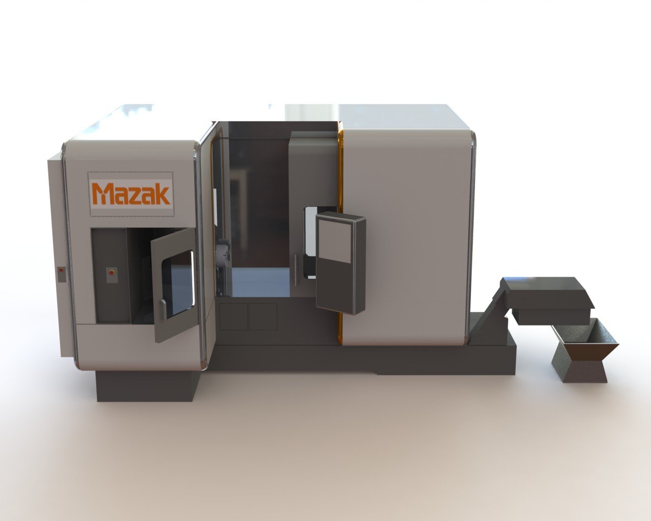
HI ALL, I have modeled an Integrex I-200S, I have the machine assembled in the front plane in a separate mastercam file. The first issue that I am currently having is that the milling tools and lathe tools come in to the simulation 90 degrees apart, I would like them to be the same orientation as the Milling tools. This is the first machine that I have assembled so I am not even sure if it is set-up correctly. The toolpaths look right. The second issue I am having is, that on Mastercam 2019 I have been able to verify all the toolpaths both lathe and milling, despite the tool coming in 90 degrees off. However on Mcam 2020 I am only able to simulate a select group of turning paths, it seems like i can only simulate the ones that I drew custom 3D tools for. The file being used to compare 2019 and 2020 is exactly the same minus the version year. -Thanks