


racingjas
-
Posts
14 -
Joined
-
Last visited
Content Type
Profiles
Forums
Downloads
Store
eMastercam Wiki
Blogs
Gallery
Events
Posts posted by racingjas
-
-
On 3/31/2020 at 2:33 PM, AMCNitro said:
Like that? Im terrible with written instructions...
thats correct but all walls .045 chmf and 8.5 draft into center as shown in flat profile
thx for your input
-
On 3/31/2020 at 7:28 AM, 5th Axis CGI said:
Are thinking correctly in your approach? Are you rolling or unrolling the flat pattern? With Rolldies you have to take the unrolled shape into account how it will be once imprinted into the final shape. Is Level 21 the unrolled pattern? If not then you would not project it to the rolled pattern like your attempting. You would take the shape and roll it using transform/roll then the 5.7295 Radius or the 11.459 Diameter would be used to roll the shape. You would then work from that rolled shape. Your approach is correct with making surfaces and then thicken them, but you need to work with the rolled shape of the finished product not the flat product to get what your after. May have to surface model it all up to make your male Boolean removal solid then once you have made a watertight surface model to represent your shape then you can Boolean remove it from the solid. Take into account your rotation and number of additional cuts out in your unrolled pattern. When I did this with Pencil and Paper 30 years ago Circumference = 2 * π * r is one of your 1st thing to think about. Then remember you working in Radians so you need to take length and divide it by 360 to come up with the distance along your Diameter that equals one degree. Once you know the length of your flat pattern for each shape then you can see how to arrange the correct number and spacing needed for your final roll pattern shape. Most people have already done this, but there have been times over the years where people had an idea and they were wrong and I had to remodel their rolldie shapes for them to get it correct. If it is an odd number per rolldie then take the rounding error into account. Small numbers harder to see the rounding error, but on larger rolldie shapes easier to see the rounding error. Need to make sure the flat pattern starts and ends correctly. If you need to spread the error then make sure your taking that spread into account across the flat pattern considering start and finish overlap. Sorry don't have whatever version of Mastercam your using and can only save as a 2020 version.
Thanks so much for your advice! i did exactly that and it worked like a charm!
-
CAN SOMEONE PLEASE HELP ME MODELLING THIS DIE?
I AM STRUGGLING TO ADD A 45 DEG DRAFT SURFACES TO .04 CUTTING EDGE
AND AN 8.5 DEG DRAFT TO .200 EDGE
HOW CAN I ACHIEVE THIS? WHAT AM I DOING WRONG?
LEVEL 21 FLAT VIEW GIVES YOU AN IDEA I HOPE OF WHAT I MEAN
THX IN ADVANCE FOR YOUR HELP
-
On 2/22/2019 at 3:29 PM, LESS said:
Boolean Add
Or
Boolean Remove
_____________________________________________________________________________________________________________________________________________________
1. Project your fonts on to the sphere ( solid )
2. Create solid sheets from trimming surfaces with your font's wire frames
3. Thicken sheets in what ever direction you want ( Emboss or Engrave ) and however much you want .
4. Boolean add or Boolean remove will depend on what result you wish.
___________________________________________________________________________________________________________________________________________________
These images are a 10" sphere with lettering embossed .500 high and engraved .500 deep.


Hello less,
that is exactly what I’m trying to accomplish!
You lost me at create sheet solid, I’m missing something. I understand thicken and Boolean add/ remove. I am. personally struggling with creating the sheet solid.
Woukd you you make a video or please explain further? Your help is much appreciated
-
Hello,
i am wondering how is it possible to extrude cut body a font on to a solid sphere so that the font has equal depth.
If I project the font onto a solid sphere. It does not let me extrude a non planar chain.
So now what?
Thanks in advance for all your help
-
Hi guys,
while milling circles for example in surface finish contour my parts are coming out with facets. It happens as well on non circular features.
How the heck do I stop this?
Thx in advance and I appreciate all the help.
-
20 hours ago, C^Millman said:
I took your flat pattern and I made it the complete pattern. I then rolled it to the 9.072 Diameter. I then Dynamically transformed it to put on top of your solid. From there I would use it to road map the Solid you need to make. Roll Dies are sometimes best left in the flat pattern and machined that way verse trying to make the solid that represents it. That is not an easy solid to do in a good professional level CAD software IMHO. Might could spend a day and figure out a way to make the solid, but I would just leave it a flat pattern and machine it from there.
I would like to see what a good Solidworks, SpaceClaim or other CAD guy could do with this. I am not saying it cannot be done in Mastercam, just will be some work to make it the correct solid.

thanks so much for all your input!
-
6 hours ago, pullo said:
nice job pullo!!! thanks so much for all your help!
-
18 hours ago, ajmer said:
take a look at this file
I used the 2 rail method that leigh mentioned
I did it in 2018 so I saved it as a step aswell
thank you very much for all your help!
one question,how did you greate the upper arc? projection?
-
sorry guys,not sure what happened with my previous file
I uploaded another so I hope that works this time
-
Hi, I sorry guys but some of the levels may be turned off. Double check the level manager.
-
Hello guys, I haven’t finished the model....... that’s why I’m here.
Jlw, the geometry was all created by me as per the drawing, not taken from a solid model.
there is no solid model available, that’s why I’m making one. The partial model I created was enclosed in the mcam file.
85 people view this and no one can help?? Come on boys, someone must know what’s happening!
-
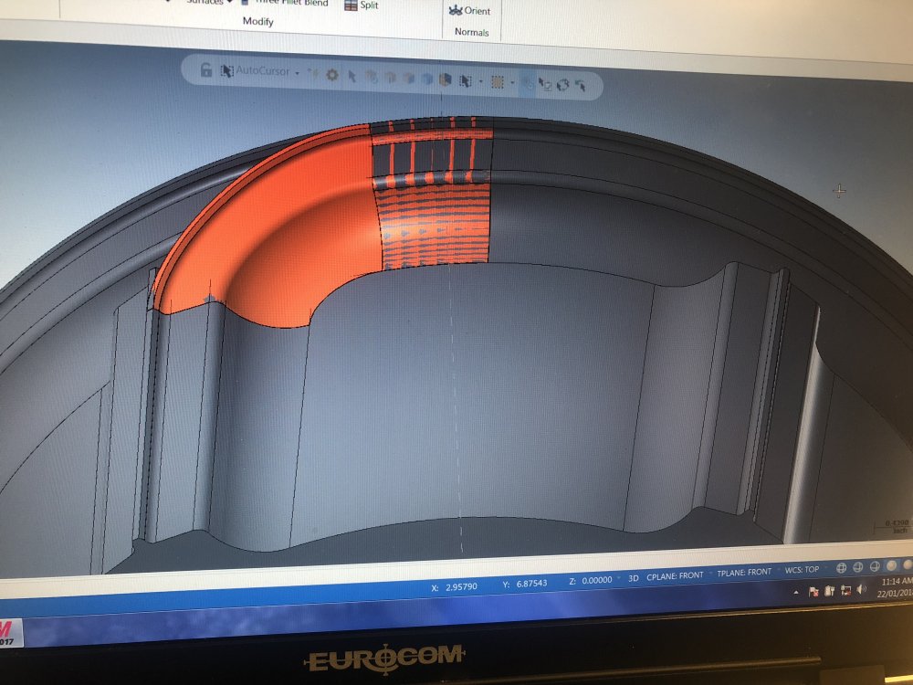
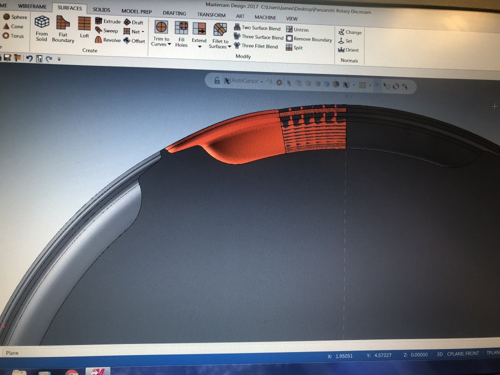
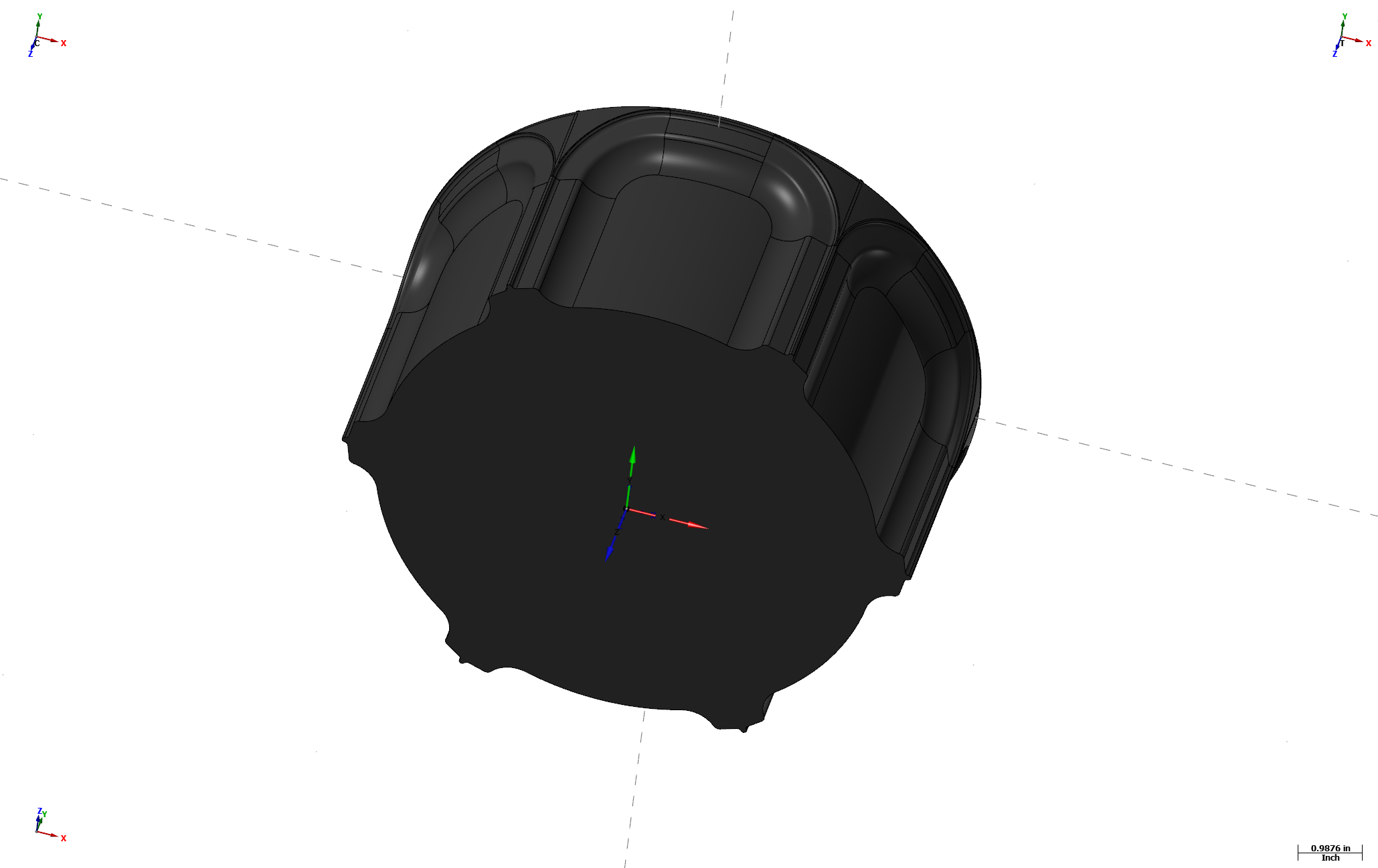
Calling all Mastercam modeling wizards.
We are new to solid modeling and are struggling to complete this corner on this model.
I have extruded the front portion, revolved a portion in the rear and am struggling to sweep the rads and have them join smoothly.
Ahhhhhh!
If you look from the rear view it appears that my surface actually goes beyond the outside diameter.
Some please point me in the right direction.
I have enclosed the mcam file and a couple of pics.any help would be GREATLY APPRECIATED!
Thanks in advance.
NPD-0102 - 4.75in Panzarotti Rotary Die.mcam


PLEASE HELP!!!! CALLING ON ALL SOLID MASTER'S
in Industrial Forum
Posted
thx ernie, i wasnt aware of that