


jonathan joseph
-
Posts
70 -
Joined
-
Last visited
-
Days Won
1
Content Type
Profiles
Forums
Downloads
Store
eMastercam Wiki
Blogs
Gallery
Events
Posts posted by jonathan joseph
-
-
Hi all,
I use Mastercam router and I'm used to having a certain toolbar available to me. Today mid-day I opened a new file and the tool bar is gone and I can't get it back. I feel like this has happened in the past and all I needed to do was go to settings/load workspace and then select router and it all came back. That's not working. I went into settings/configuration/start up/exit and made sure startup and workspace was set to router, still nothing. Restarted computer etc.
I've tried a bunch of different files and they're all the same.
Suggestions?
Thanks!
Jonathan
-
On 9/15/2022 at 12:58 PM, Aaron Eberhard said:
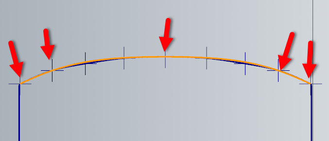
Looking at the points your spline was made from (create Points > Node Points), then creating lines between them reveals that there's an inconsistent angle between the points, which means you're not going to have a "smooth" spline, as it has to conform to each points different.
If this isn't a high tolerance part (and I'm sure it's not as you're only making 9 points across 53"), so I'd recommend just not using the odd points.
In this image, I made the orange spline by only using the points from the points indicated by arrows. Much smoother as it doesn't "tuck in" to hit the points not on the "arc" that I want to hit.
Aaron, thank you very much for the suggestion. Sorry to not have followed up sooner. I appreciate all the help here.
-
 2
2
-
-
Sorry to not follow up on this post. I greatly appreciate all the attempts to help. It turned out that I had a mechanical problem on my z axis. The z-axis ball screw upper bearing block had a lock nut that had come loose and the bearing was literally moving up and down. It would jam all the way up when the spindle rose up to max z then stay there for a while but eventually work its way back down. Fixed now.
Thanks again
Jonathan
-
1
-
-
5 hours ago, TFarrell9 said:
I'd use a Manual Entry instead of a dwell, assuming you're saying the vacuum table shuts off at the end of the program.
After the last toolpath: Router Toolpaths>Manual Entry>*type* M0
Then when the operator is done blowing it off, they can hit Cycle Start and the the remainder of the program will be ran.
Thanks! I'm still having a problem finding the right place to insert the M0 because my post uses what I guess you would call canned cycles maybe? There is a M73 that I believe raises the z, takes the gantry to park, and a few other things like opening and closing some blast gates for the dust collection. I've tried putting the M0 after the M05 and M06 and before the M73 then after the M73 but before M140 which is shut off all vacuum zones but the program keeps stopping as soon as the last part is done being cut. Can't get it to do what it normally does and return to park and then pause. Not sure it will help without understanding my controller but I've attached the file.
-
I run routers and need to be able to program a pause before my vacuum table shuts off in order to have time to blow off the parts with air. These are thin lightweight parts with masking and if they aren't held down by vacuum they blow around and the masking comes off. One of my machines has a convenient vacuum on/off push button but another does not and you have to scroll through a long menu to manually switch on and off. Long term solution is to install some solenoid control switches but I can't get to that right now. A 20 or 30 second pause will give the operator time to clean them off before off loading.
Thanks in advance!
Jonathan
-
I'm using a sacrificial spoil board on a router. Top of my spoil board is zero. Most all of my cutting is positive except when I want to cut all the way through the material into the board then I go negative. It's just the way I learned. I think it's pretty common on routers?
-
Sorry let me clarify a little. It is plunging into the material and starting the ramp .5 lower than it should. starts ramp at about .25. Feed plane is set to 1". Top of stock to .75". Depth of cut to .025.
It did in fact though cut into my table almost .5 deep. Despite not showing that in the program.
You can see the difference in height at the start of the ramp between the two different tool paths despite them both being in the same operation
-
Probably just a rookie mistake but I've got a program that is not running at the depth programmed. 32 parts on a 48x96 sheet of plastic on a router. Using X8 ( I know it's old, but it works for me every day usually)
The first row of parts for some reason want to run about .5" deeper than the rest. When I switch my view to the front and I use backplot to simulate it I can see the depth of the toolpath on the first row of parts is different and deeper than the rest. They are all in the same operation using the same parameters so I'm lost. What am I doing wrong? I started to run it on the machine but quickly realized it was way too deep.
Thanks in advance as always.
Jonathan
-
Here's the file, thanks for looking at this!
-
Amateur question I'm sure. I just made a spline using "manual spline" in X8. I drew 7 points to draw the spline through. When done the spline was faceted not smooth. In the past I've done this with no problem. What am I doing wrong?
Thanks!
-
Dynamic Xform only seems to let me move it in. X and y and rotate.It’s turned up in the z also. How do I get that to change?
-
All I have is the dxf right now
I open that in MC and it’s skewed
-
Hi all. It’s me the novice again. I just received a file that is 3-D and I only work in 2d and I can’t seem to figure out how to turn the part to true top view only. It is currently skewed a little. I’ve attached the file. Can anyone help?
Big thanks in advance.
Jonathan -
2 hours ago, #Rekd™ said:
There are free courses at Mastercam University, likely though in a newer version. The Sitewide subscription here is also a great choice, you can go at your own pace.
Nothing wrong with being self taught, gaining knowledge/ skills any way shape or form is a good thing!
Thanks again! I definitely would like to take some classes, and learn what I don't know I need to learn. Just hard making the time while doing the work, trying to manage and grow a business and having a family....not enough hours in the day!
-
1
-
-
40 minutes ago, crazy^millman said:
You work in 3D all the time the problem is you're limiting your thinking process to only 2D. When I train new programmers I always tell them they have been programming for a long time. They all look at me like I am crazy or something. I tell them without realizing it they make CNC Programs all day everyday in every action they take or make. Go to open the fridge and get some milk out of the fridge. That is a a program your brain tells your body to preform without you even thinking about it in 3D space not 2D. Get in a car and drive somewhere you are driving in 3D space not 2D space. Everything we do is 3D and don't limit your thinking to what you think you cannot do to what you are already doing. In Mastercam working in 3D is no different. Stop and think the process through and really understand that even though you make only see a 2D wireframe that will have to cut at different depths. Those depths are not only ever going to be at Z Zero they will can be above or below Zero and that is 3D space not 2D.
Yes of course. I appreciate the comment. I definitely think in 3d, just outside of normal depth of cut issues I don't really know how to do much. I do some pretty tricky 2d stuff that requires a lot of thinking, not just simple 2d shapes. Lots of specialty bit profiles and multiple depth cuts to create unusual edge profiles etc. Lots of thick material with all kinds of different pockets and depths.
-
45 minutes ago, #Rekd™ said:
I don't have X8 loaded but I created a video using X9. Watch this video for some ideas, there are many ways of doing things.
Getting some training would be a huge help to you and your company.
I really appreciate the help. Training would be great but honestly I'm self taught and have been running a company doing production routing with five cnc routers for seven years. Rarely and I mean rarely have I ever needed more than I've learned already. There have been a few humps to get over but I make parts as fast or faster and efficiently as any of my competition. It's kind of like languages. I'm fluent enough to get done what I need. Every couple of months I get a curveball like this, and usually the forum helps me solve it.
-
1
-
-
Also, I don't know how to "select a surface" or new level as you say? I don't do anything 3d so this is new to me.
-
16 minutes ago, #Rekd™ said:
On a new level, use Create - Curve - On One Edge. Then select the edges of the holes you want to apply the "Curve" on.
There are corrupt entities inside your file (warning message when I opened it).
Some of the Solids are sitting above Z zero and some are sitting at Z zero.
Thanks! SO the things sitting above zero are going to be a problem too I suspect because they're not at origin. How do I resolve that?
-
Hi all
I've gotten some help with this before but my problem is back. I'm trying to work with a solid model but only have Mastercam router x8. Trying to just do a 2d contour but having trouble being able to select just the contour lines. I was able to fix this by using the "silhouette boundaries" function but I still have some geometry, circles mostly that I can't select. See attached file. Outside of the parts is fine but some, not all of the holes won't let me work with them.
Any help appreciated.
Jonathan
-
On 6/7/2021 at 7:18 AM, Rich Thomas 4D Engineering said:
I opened X8, drew five rectangles and chained them in a single contour op. I then went to the Geometry section in the Toolpath Manager which pops up the Chain Manager window, and used the CTRL key on the keyboard to select two of those chain. The small square chain icons went darker in colour than the three remaining chain icons. When I pressed the Delete key on the keyboard, the two chains disappeared from the list.
So using the Control key method works for me, not sure why it wouldn't work at your end, sorry.
Humm, maybe its the computer I'm using. Don't know why that would be. I'll try on a different one.
-
I would have thought the same, like in any Windows program but it doesn't work in Mastercam for me.
-
Is there a way to delete multiple chains at a time? Some times I need to restart a program in the middle (usually because the machine has errored out for some reason or someone hits the e stop by accident. I usually open the chain manager and delete all the chains that are finished and re-post. But I can only delete one at a time and it takes forever to regenerate after each one. If there aren't alot of chains I'll just re-chain all and start over but often there can be hundreds and it takes forever. Using X8 router
Thanks
-
22 hours ago, Colin Gilchrist said:
What kind of File Format are they giving you? That looks like a bad IGES or DXF Translation.
Ask the company for a copy of the 'Native File', or ask them to export a 'STEP' file.
If you have a solid or surface model, you can generate your own wireframe from those solid/surface edges with the 'Create Curve' command. If the model is a Solid, you won't need to however, as Mastercam will recognize the 'holes' as 'circles', and let you pick the center point.
This is just a result of bad CAD Data translation.
Colin
I receive a dxf from them. Not sure what they originally create them in. I'm pretty primitive and only work in 2-d up to now.
-
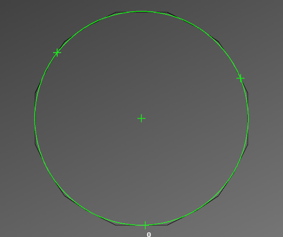
15 minutes ago, Ocean Lacky™ said:
Your 'circle' consists of a bunch of short, line segments.
Place 3 points around the 'circle' and use those with Circle/Edge Point-3 points command.
From there you can come close
That's great! Thanks! Any idea how they generate a crappy circle like that? These are supposed to be serious businesses, I'd assume they have better software than me.....
Load workspace problem
in Industrial Forum
Posted
I think you got it! When I logged in this morning and for some reason I couldn't get into the correct user on my pc.