RESISTER
-
Posts
4 -
Joined
-
Last visited
RESISTER's Achievements
")
Newbie (1/14)
0
Reputation
-
Yup, it was the probe. It was dancing around like crazy. Doing the recalibration now . Tnx everyone for responds
-
There is no bowing . The part is set up rigidly . One extra chamfer in OP1 is because i chamfer the inner side of the holes which are not visible on the other side, countersinked holes. And i use the corner zero on the second operation because its faster to set up for the operater and so far i havent had the inaccuracy problems. The thing is even if i go for the middle of the part zero, nothing changes. I tried. All the measurments were ok from the first operation. I havent checked if theres somekind of missaligment on the first operation, offset wise. It has to be something with offsets but im not sure what. Ive tried another part...put my zero offset in the middle of it. Tiny round part fi10. Positioned the machine with reinshaw probe to the middle of it. ..should just mill it on both sides for appx. 1.5mm and its way off. Same stuff as above . Set the diference in offset on machine and then did as it should. Why does that happen? Is it posible the probe measures incorectly?
-
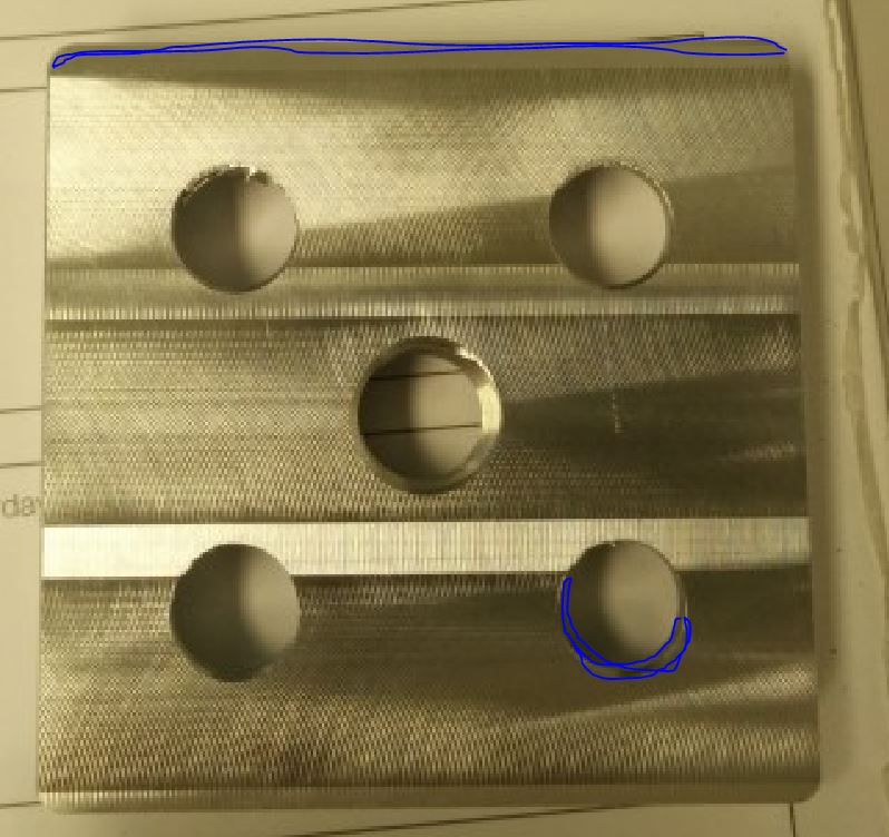
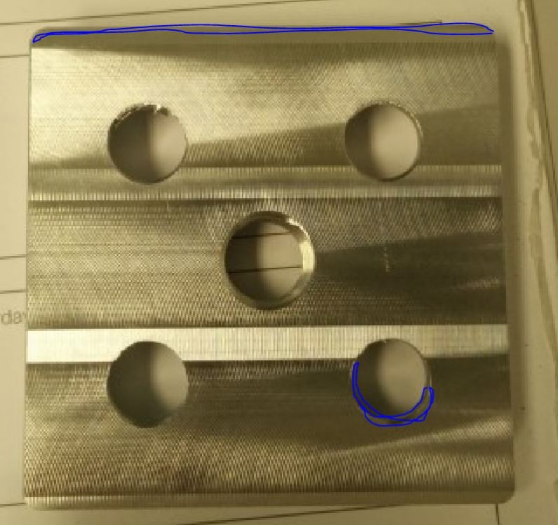
You mean g-code? 170630-091 VP1 chamfer.NC170630-091 VP2 chamfer.NC Here they are just for chamfering . I checked the code, run simulation, verify, everything looks ok from my(programing) point of view... We've run the multiple setups and adjustments at the machine itself...everything looks ok. Heres the actual part and how chamfer is made. Sorry for poor quality .
-
Hello. Im running out of ideas so i decided i would ask on this forum about my "experiance". Recently we've come across an interesting chamfer feature after trying to chamfer the other side of the part (2nd operation)...and its repeating on every part. The chamfer is missaligned . I dont even know how to explain it... lets say im trying to chamfer a square and a hole 0.5mm equally. When i do it on the first operation that works perfectlly fine but after the second operation( when you turn the part around for the facing and chamfering the other side) the chamfer is wrong to say the least . The chamfer is ...well...like it would be offseted or something and the direction excludes the operators mistake/inacuracy of positioning. for example it would be -1.5 in +y direction(biger champfer on north side of square) and none existent in -y direction on the outside conture(square) and completly opposite on the inside(hole) , -1.5 in -y direction(biger chamfer on south side of the hole). Im using mastercam x9 to program and haas vm3 is the machine. Tool is D=8 carbide chamfer mill and up until a week or so ago...everything was how it was suppose to be. The programed code is excatlly the same as it was the tool was replaced but there shouldnt be a difference. The anomaly just makes no logic to me. Perfect chamfer on first operation and this ...abomination on second. Can anyone shed some light on me ?