


AWL304
-
Posts
45 -
Joined
-
Last visited
Content Type
Profiles
Forums
Downloads
Store
eMastercam Wiki
Blogs
Gallery
Events
Posts posted by AWL304
-
-
I'm wondering if there is a way to extend the tool to cut below the lower rail selected, for example running around a chamfer so that
the tool is not at the exact bottom of the chamfer. i know i can extend the surface/GEO, but that can become alot of work instead of just using the model features.
using toolpath "SWARF MILLING" MC2022
OOPS
seen a recent post asking simular question, ill see if anything on that post helps
-
4 minutes ago, gcode said:
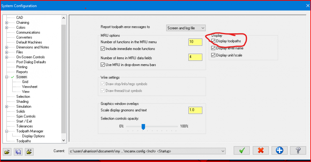
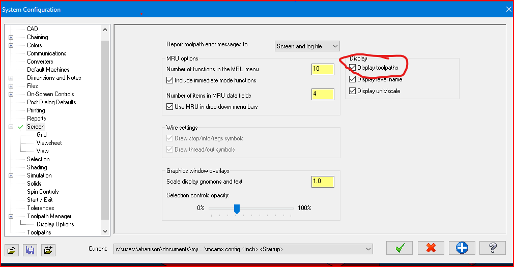
Do you have "Display Toolpath" enabled on the Screen page of System Config
I do now
its working
-
 2
2
-
-
THANK YOU !!!!!
3 minutes ago, AHarrison1 said:Goto System Configuration - Screen - Check box for Display toolpaths.
-
ok i'm missing something,
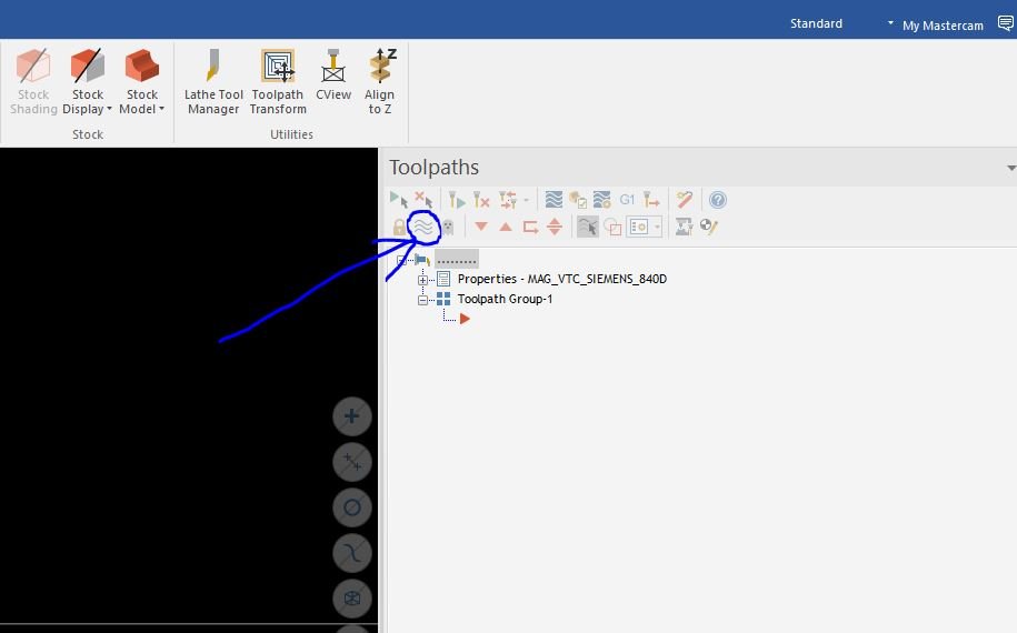
Ever since I've gone to MC 2022 the button circle in the attached does nothing. magically i noticed it was working yesterday, today not working,
what am a doing or not doing to get this to work.
-
THANKS GUYS,
our tooling guys came through just now
got taps and drills from OSG
-
1
-
-
6 minutes ago, gcode said:
I have this already, my problem is i need up to 5/8-11
sizes are:
5/8-11
3/8-16
1/5-13
1/4-20
-
Looking for a chart or formula for tap drill sizes, or ranges, for STI threads but roll form or cold form tapping .
-
15 minutes ago, Chally72 said:
I made a little video to talk about creating, linking, and associating planes. There's a much better video coming on our official channel later this year, but this gives you all the important info about the cool stuff you can do with plane linking in 2022:
Good video thanks
-
I have created multiple different planes from multiple surfaces of a solid model. we now we are moving the job from one machine to another,
where now the top plane needs to be the front or whatever. but after translating and rotating things to their new place, the created planes do not move/follow the origan from where they were created.
There must be a way for the custom planes to stay relative to a surface or model it was created from. Or is there a way planes should be created from the start
next time so this process is easier to transition?
-
4 minutes ago, crazy^millman said:
You needed to included your post in that z2g for someone to see what is going on with your post.
TRY THIS ?
I HAVE POST PROCESSORS CHECKED WHEN CREATING THE ZIP TO GO
-
12 hours ago, Colin Gilchrist said:
That error message is basically telling us that you've got a Machine Definition which doesn't match your WCS/Tplane/Cplane setup. So the Z-Axis of the WCS/Tplane is not aligned to the Z-Axis orientation of the Machine Definition.
Or, there is a bug in Mastercam.
The former is more likely than the latter, but bugs do occur.
You should create a Zip to Go file, and attach it to this thread...
Appreciate someone taking a look
-
5 hours ago, Colin Gilchrist said:
What do you have selected for your Axis Combination?
Save your file, and close it.
Use the Machine Definition Manager to open the Machine Definition.
Open the Axis Combinations Dialog Box.
Right-Click in the Axis Combinations area (white area), and choose "New Axis Combination".
In the "kinematic tree", choose the X, Y, and Z Axes, and check the "spindle", and "machine table". This gives you a "work holding component", and a "tool holding component".
Name the 2nd Axis Combination as "3-Axis".
Save the Machine Definition.
Open your Mastercam File, and do a "replace" on the Machine Definition.
Open your Operation, go to the Axis Combinations, and select "3-Axis".
Check your Planes, and make sure that WCS, Tplane, and Cplane are all set equal.
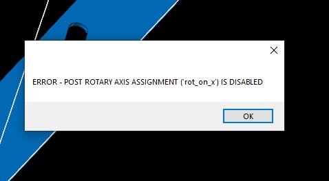
ok just got back to this.....I did what you explained, i was able tp create and select the new axis combination, but still get the first error. " rot_on _x is disabled etc.
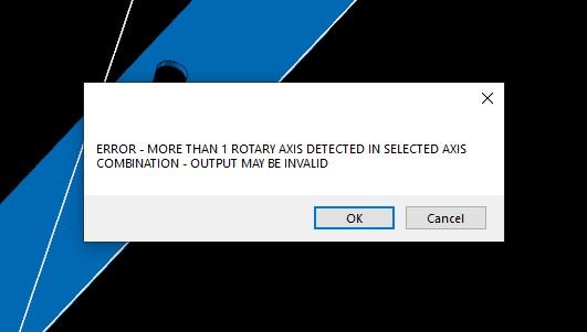
the second error no longer comes up.
-
yes i did
-
I'm using a morph tool path for 3 axis machine, but when i go to post i get these errors. is this my post? or am i missing a hidden setting somewhere?
-
10 minutes ago, gcode said:
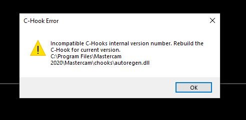
I believe this chook was written by a forum member and is not supported by CNC Software
Try searching the forum and see if the author has updated it to MC2020
yes, i found the original post, just didnt notice the second page....oops
i see hes been updating, im just behind
thanks
-
Im going into MCAM2020 and trying to transfer things, ihave a chook i like to use, so i copied the .dll & .ft files to the chooks folder. When i try to run it i get this error.
how do i "rebuild" the files for 2020??
if thats my problem
thnaks
-
So.....
i got kinda what i wanted using standard drilling tool paths then using the multi axis linking, and it works, but its a bit more work. seems like you should be able
to do do this with multi axis drilling all in one tooplath, isn't that the point?
-
i am drilling holes on three different sides of a part, im using multi axis to do this but when drilling holes on top then when it goes to the sides, it rapids through
the part, backplot & posted code, it sounds like the safety distance is what i want but it seems to do nothing.
what am i missing??
-
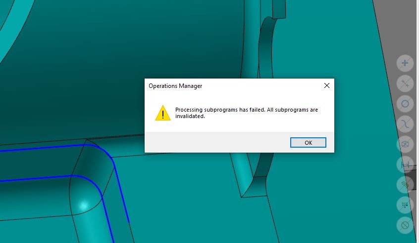
see attached....
Can anyone tell me what is causing this ?
I deleted a coupled stk models, not attached to tool paths, and now when trying to post ANY type of path i get this before it just post the code anyways.
i have zero tool paths with subprograms before you ask, as the warning imply's
-
50 minutes ago, 5th Axis CGI said:
You have run into what is called a singularity event and to be expect when doing exactly what your trying to do. That function doesn't take Kinematics into account in the operations itself. The post however is taking Kinematics into account an you have hit the infinite place where the endless solutions at X,Y,Z,A,c have just happened or what we call a singularity event. The post it letting you know your machine can do some unexpected things. The best to avoid this is put your fixture on a 5 deg tilt so the part is not for the majority of the work ever at X,Y,Z,A,C zero at the same time. When it is where you thought it was going to go clockwise it may go clockwise or vice verse or the other thing is 5 cuts go clockwise and look great then you get to the next one cut that is counterclockwise and boom you have a crash.
The post is doing exactly what it should be doing. Now you have to decide do you want to modify your process to eliminate this issue by putting the part on a slight angel to not allow it or rethink the toolpath and approach it another way?

OK....
i did just that i created a plane 5 degree off my normal plane and ran the tool path from that plane an it posted without error.
thanks!!
-
well, maybe i follow....
i have noticed it puts the warning message in exactly after the lead in moves, retracts than goes back in to Cary out the tool path with no problem.
You say to run it at an angle, i have no "A' axis but if i were to create a plane as to rotate my "b" on say a 5 degree angle and run the too path from that plane, this would accomplish the same as you mentioned?
i will try this if i explained it rite.
-
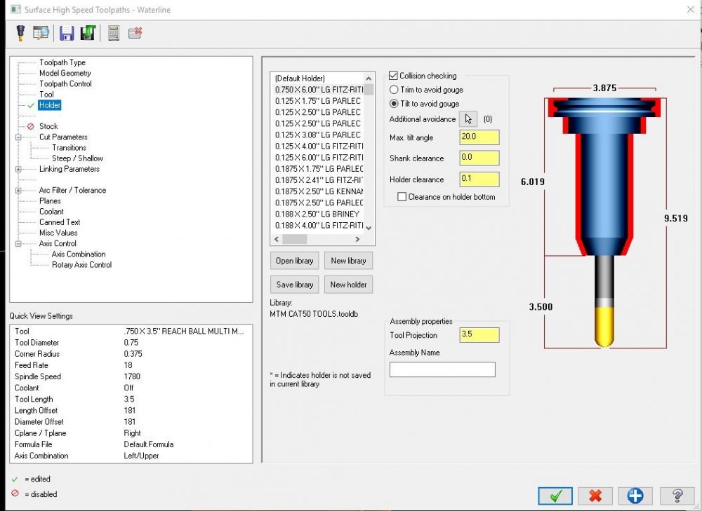
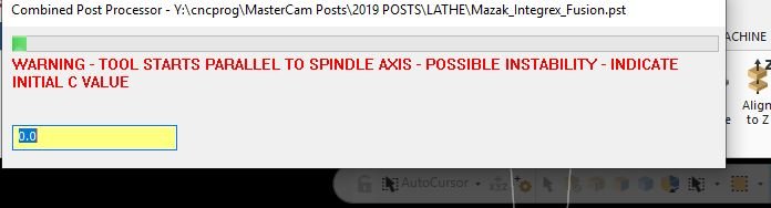
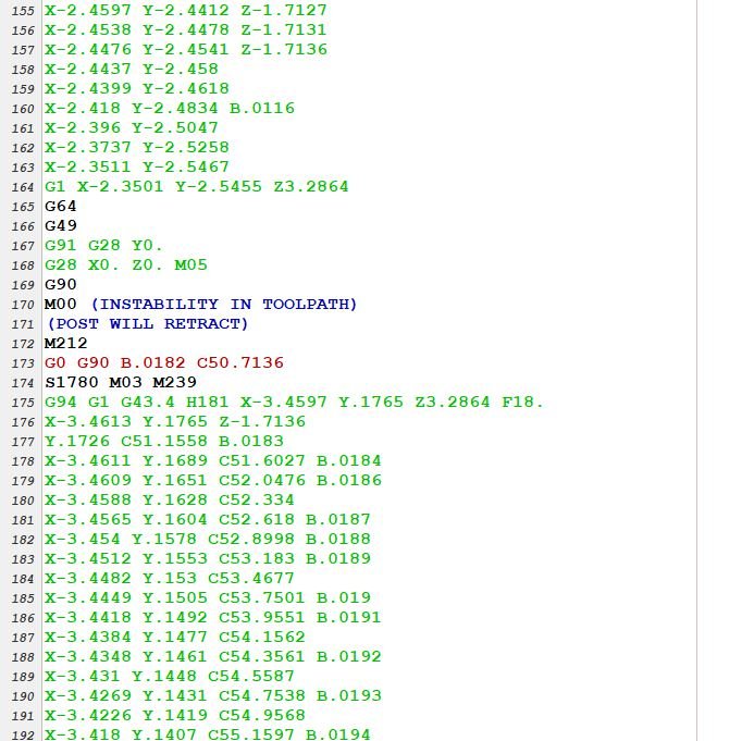
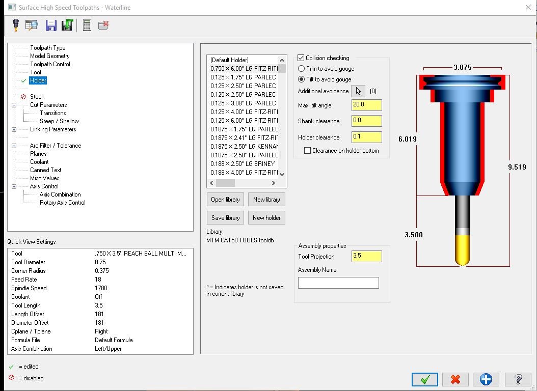
I have never used this feature in the high speed paths, but it seems to work great. except after hitting the post button I get this warning, it
post just fine but inserts a "instability in tool path" warning in the actual post. I think its retracting to avoid something, and also before any "c" moves start, why?
the machine does run it if you keep hitting "GO" it skips rite thru it and carries on, besides going home then feeding ALL the way back to position.
is there a way to avoid this warning??
tool path: waterline
machine: mazak integrex
-
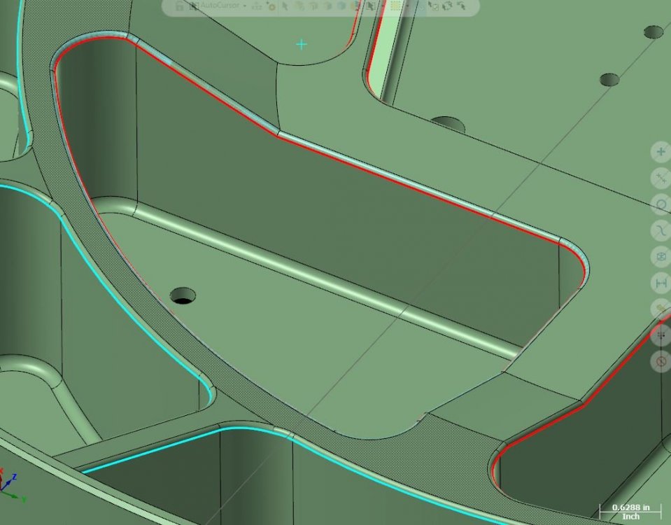
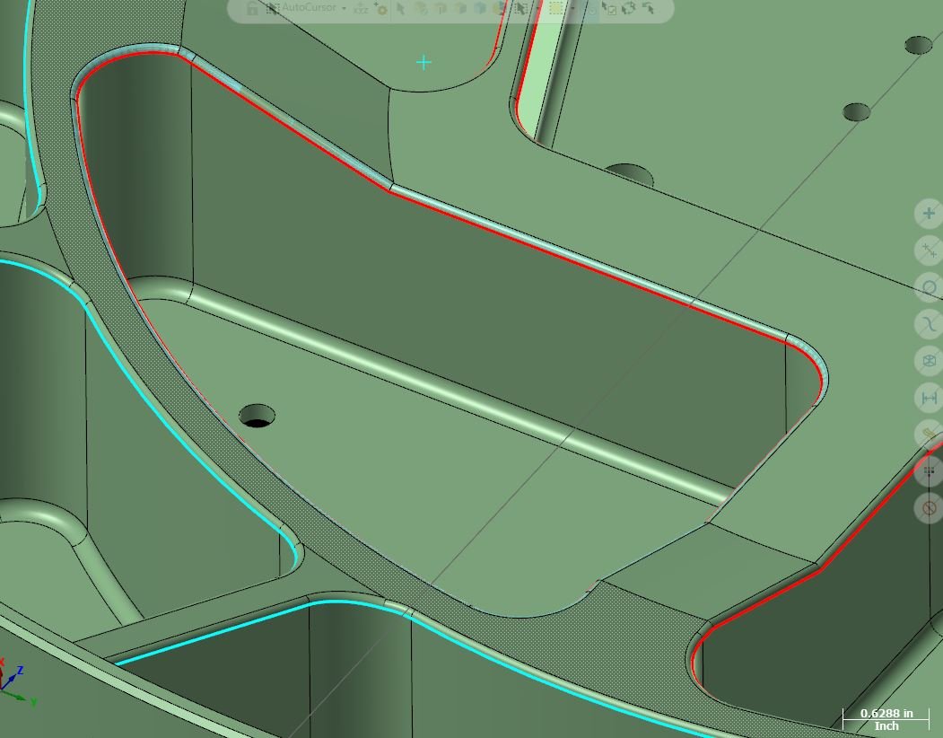
I have to finish the small rads running along the top of my pockets ( attached pic), i would love to simply spiral a ball around the edge from top to bottom.
the surfaces do not line up perfectly in several spots because of the angle and radius transitions. The only thing i have gotten to work is 5axis "along curve", but
its wants to run vertically along the edge (perpendicular to the red line).
any ideas? is there a way to get the along curve path to run with the curves and not orthogonal.
machine: 5 axis integrex
-
On 6/6/2019 at 2:34 PM, 5th Axis CGI said:
You really didn't want Comp output?
i WAS looking for comp output but am told not possible?
swarf milling-extend beyond lower rail-
in Industrial Forum
Posted
YEP
got it now thank all
should have read the earlier post, was already answered for me