MGF
-
Posts
14 -
Joined
-
Last visited
MGF's Achievements
")
Newbie (1/14)
1
Reputation
-
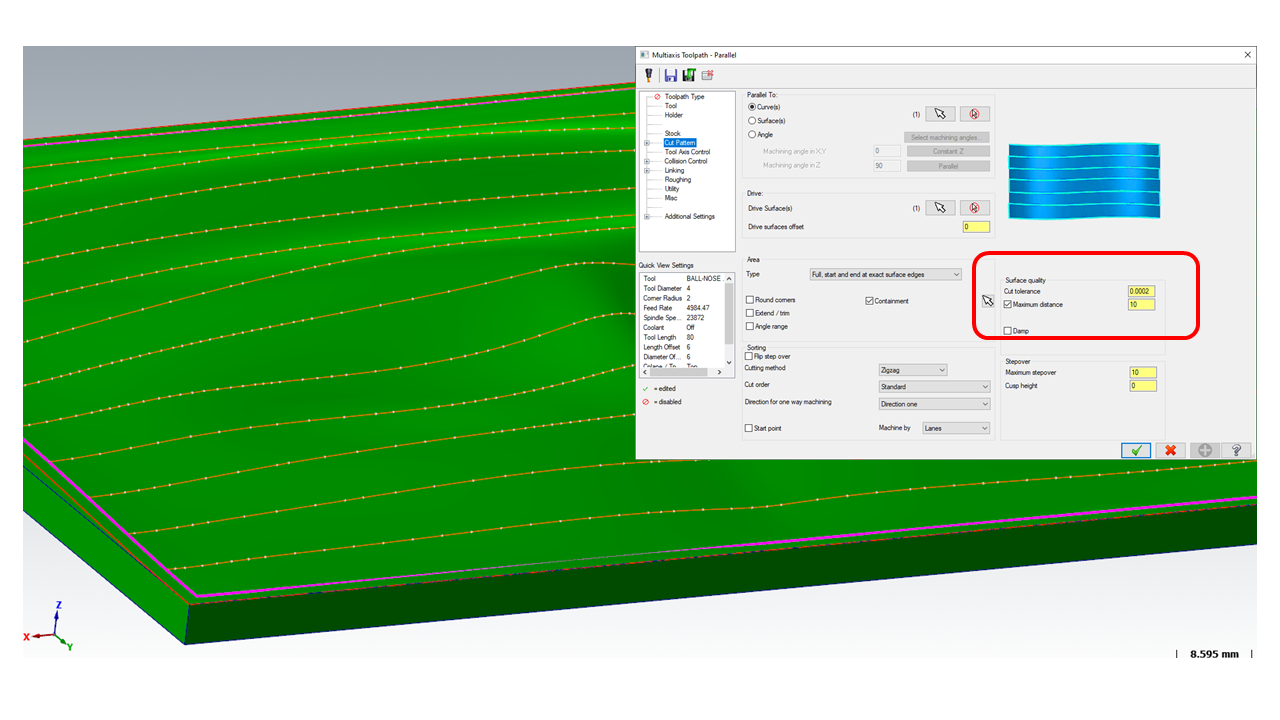
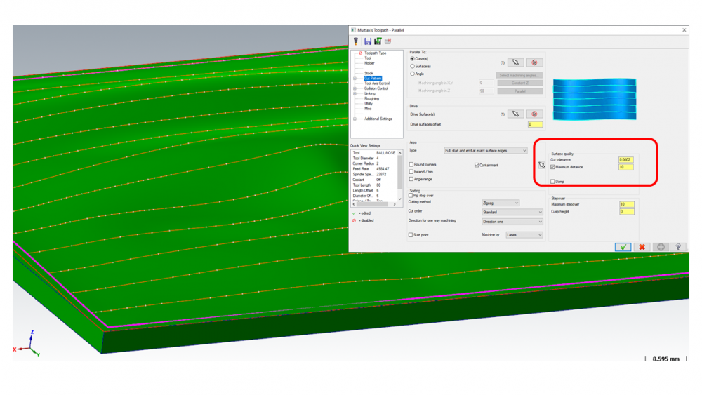
Hello! OK, I think I found that the Cut tolerance parameter was wrong. Best regards. Mitja
-
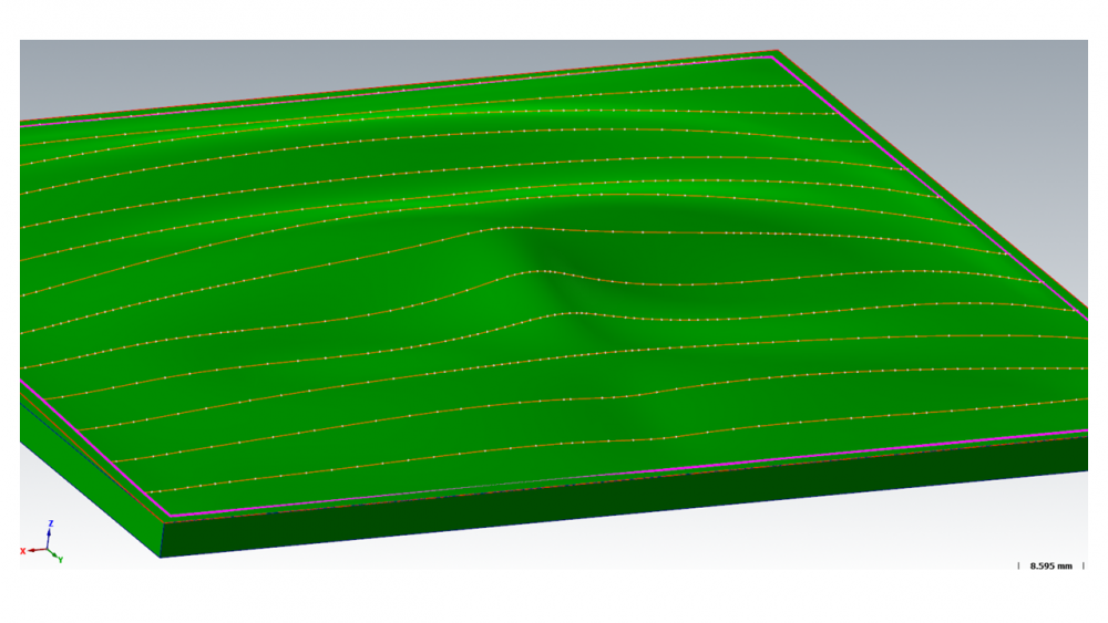
Hello! So I predicted, but if I look at the image below (step 10 mm) the points are different apart. I presume that these points are white in the picture below. There may be another parameter to be set? What exactly mean maximum distance? Thanks and best regards. Mitja
-
Hello! Below I attach a 3D model image showing the tool path. I am currently using the Multiaxis-Parallel strategy. This strategy supports all of our requirements. I just want to know how can I define a specified distance (for example constant 5 mm) between points ( white points in the image ) in the toolpath. Currently, the distance is not constant. Does any other equivalent strategy offer this option? Thanks for the help and best regards! Mitja
-
Hello! Does anyone know what could be the problem. Would be very happy with any help. Best regards. MGF
-
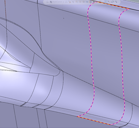
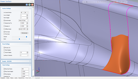
Hello! Maybe someone knows why if I do a surface projection (left picture) and then based on that projection I would like to generate a new surface (right picture) I don't get the same surface as the original. See the pictures below . Thanks for help and best regards. MGF.
-
Hello! All right, now I've done it. I only want to know this: in your case, the offset surface was made up of three pieces - how you put them together into one. Best regards. MGF.
-
Hello! Could you please tell me exactly which command you used to create the offset surface. Thanks and best regards. MGF.
-
Hello! Ok, thanks for the info. I'll try. Best regards. MGF.
-
Hello! Thanks for your response and help. This is exactly what we needed. I only wonder if you can briefly describe how you created a cleaner and simpler 'pattern surfaces'. I tried it myself, but it does not work. Best Regards. MGF.
-
Hello! Thanks for your reply. We do not have much experience with this which strategy would produce better results. Which strategy do you think would be then more appropriate? In our opinion, it is definitely necessary to choose Multiaxis option for such part geometry - are we thinking right? Thanks for help. Best Regards. MGF.
-
Hello! Thanks for your reply. I am currently using: Toolpaths -> Multiaxis -> Multisurface -> 5 Axis Across stepover: 2.0 mm Along stepover: 2.0 mm Cutting method: ZigZag Tool axis control: Pattern surfaces Output format: 5 axis Tool Info: Ball-Nose -> Diameter 2.0 Maybe one more question: Can I merge these partial surfaces into one in the MasterCam? Best Regards. MGF.
-
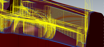
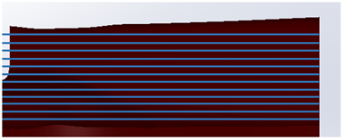
Hello! A while back I posted a case where I got into a problem. Below I attach a picture of how the MasterCAM tool generates paths. Our wish is that the tool path would look as shown below ( without those jumps - the yellow lines in the picture above). One of the conditions is that the tool is always positioned perpendicular to the surface. Does anyone know how to do this in MasterCAM? I am also attaching a MasterCAM model. Best Regards. MGF. surface_test.mcam