StevenL
-
Posts
7 -
Joined
-
Last visited
Recent Profile Visitors
225 profile views

StevenL's Achievements
")


-
I'm at this point this morning. I talked to our machinist about running some knurls and I need to get it on MC. My first thought was exactly what I'm reading here. I'll call it a grooving tool and just run a finish pass. Thanks for the confirmation . It seemed to make sense and this forum has confirmed it.
-
Index Drill as a drill and boring bar (MasterCAM)
StevenL replied to StevenL's topic in Industrial Forum
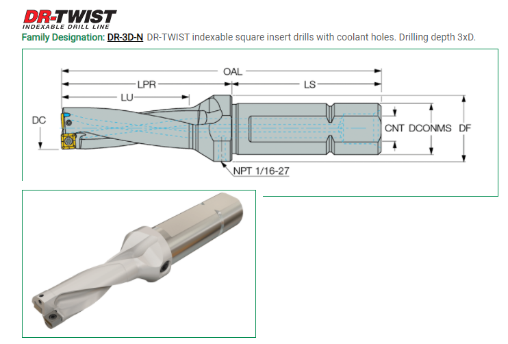
I probably should have mentioned I was talking about a HAAS CNC lathe. Thanks for all of the good information. I'm going to model it again as a drill and I received the 3D stp. file from ISCAR and I'm going to model it as a boring bar also with the proper insert. It's going to be fun. Thanks, Steve- 9 replies
-
- 2
-

-
- index drill
- boring bar
- (and 2 more)
-
I would like to use an index drill as a drill and boring bar. I can set it up like a drill in my tool library, but does anyone know the proper way to call it out being that its has offsets for a drill and also offsets as a boring bar. HAAS has a video saying you can do this, but they don't really explain much beyond that. The devil is in the details. - The process would be call out the Drill as TOOL X with offset X and drill hole. - Then call out "drill" again, but it's actually a boring bar now. It would have the offset of a boring bar. The designation would still be drill but operating as a boring bar. This gets really confusing. I almost think I have to do the tool as a boring bar separately using the insert on the outside like the tip of a boring bar. Thanks, Steve
-
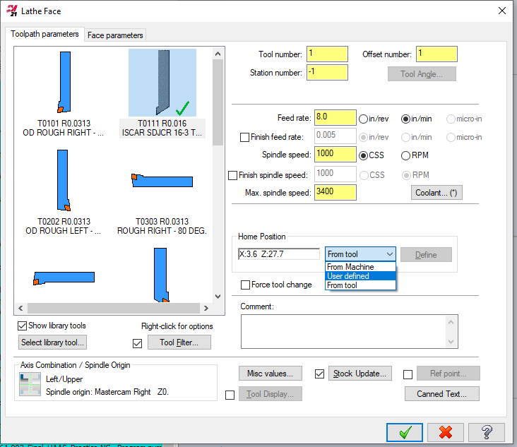
I successfully completed a class in MasterCAM as I picked up a position to allow a business to bring in work to their own CNC lathes. I talked them into purchasing MasterCAM for SolidWorks and I was pretty much on the hook to make it work. Up until now their machinist would manually enter parts via the control panel and play with arcs and flats to get a part machined. It was pretty tedious to do. I was able to quickly design parts in SolidWorks and model tools and create programs from the desktop computer. Now I carry a thumb drive to the CNC lathe and give them the tool setup and stock sizes and they start production parts as is. It's great. Now we have a second new HAAS machine (our first HAAS) and I've got the new Post Processor files and I have been able to run simulations with a new Machine Group, but there's this perplexing issues of Tool Home Position. I basically manually enter the home position values on the first machine into each tool and it seems to work. Here's the question: What exactly is the Home position? I believe it's the place the turret goes to change tools. It can be User Defined, Tool, or Machine based. I read the X and Z position off the machine when at home and I used these numbers. Is this the way to go or can I use the values pre-set in MasterCAM? I believe it's Machine is default (X:5. Z:10), Tool (what ever I programmed into the tool model). I know this should be simple but at this time clarity would be good. Steve
-
Thanks all.
-
Thanks, I put a huge number in for lead in length (5") and it cleared up my problem. I kept scaling it up in small increments thinking I wasn't way out but in the end it was somewhere between .350 and .400" needed to clear previous cuts. Sometimes the error is obvious when you simulate and you find a cone shaped part, here it just didn't show up.
-
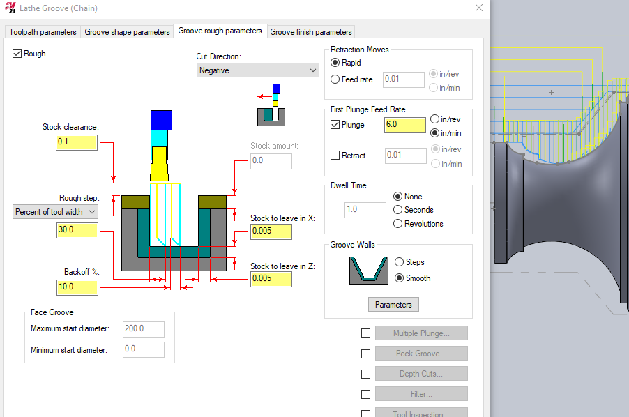
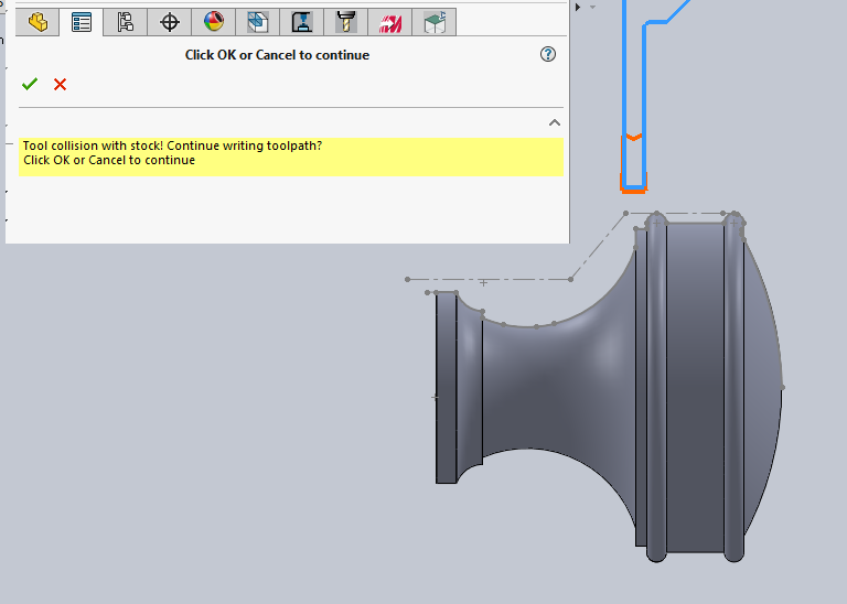
I have MasterCAM for SolidWorks (essentially MasterCAM 2021). I'm new to this in the past few months. Straight out of school to the industry. Lots of success getting cosmetically clean parts off our CNC Lathe, quickly, but I like to use lathe groove tool to make deep curved and convoluted shapes in the hardware parts. It works well but I noticed when I use the "Groove walls" option Smooth I sometimes get a collision with stock even though I know this isn't case. If I go back to "Steps" it's OK. I realize there are Entry settings with Degrees (Sweep) and (Radius) but I change these and they don't really make a difference. Has anyone else seen this issue. I like the clean form I get prior to finish because final finish is very important. Knocking off the steps on the finish cut can give a slightly rougher finish. I think I'm going to ignore this because I do a pre-rough pass using constructions profiles to "hog" out a basic stock shape to speed things up without compromising the underlying material that has to be stress free for plating and coatings. Any stress areas can show up later after polishing and finishing.