


rgrin
-
Posts
114 -
Joined
-
Last visited
-
Days Won
1
Content Type
Profiles
Forums
Downloads
Store
eMastercam Wiki
Blogs
Gallery
Events
Posts posted by rgrin
-
-
On 8/12/2023 at 6:39 AM, Newbeeee™ said:
If the component is uniform in shape, this is the component stress reliving....it has moved during the time it's been inspected>shipped>plated(temperature)>returned to Inspection for checking....
That could be, The process is we do a heat stress relieve prior to machining. Then we rough the parts and re-stress relieve prior to finish machining and then they go to plating. The material is 6061-T6 Kaiser Select, so it should be fairly stable at that point. But sometimes ya just never know. I believe the temperature we stress relieve to is around the temp of the hard anodize process. So we aren't removing any temper but we also kind of simulate the anodize process as far as the heat is concerned.
-
The .0002 flatness has to be in spec after plating. Just getting inconsistent results with plating. Some will come back fine, but the worse one was upto .0006 out of flat post plating.
The bosses being a bolt on solution post plate was asked but was denied.
Lapping could probably be an option but is outside of my wheelhouse. I know we lap some of the customers other parts. Not sure how would lap this one with the bosses being there.
-
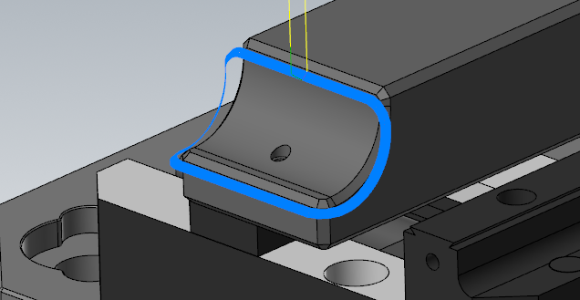
I attached a dummy part that resembles the part I am making so we can all play along lol. I highlighted the critical flatness areas in red. Basically a 17"x5" rectangle with some bosses to avoid and some islands to make co planar.
The plating is specced to be .001" penetration and .001" thick. We have successfully made the parts .0001"-.0002" pre plate using Loctite 425 ( I believe) to secure the part to a flat plate with minimal distortion. The long term issue is that we just got another order that takes our total part qty to ~150 over the next 3 or 4 months. Using our glue process is just taking too long and the results we are seeing post plating are not reliable enough to continue down that road.
I found some CBN bottom grinding mandrels from a company called DI Coat. I'm thinking I can set the part on a vertical mill and basically cam block it in similar to how our grinders would do it and then just grind it in a mill in 1 set up taking multiple .0001" Z- step downs as required.
Just looking for other options that wouldn't require a grinding wheel as I do not look forward to setting up a dressing cycle in the machine and getting grit everywhere. But it seems like our most likely option right now.
-
Hi all,
I have been tasked with figuring out a way to re-machine parts to .0002" flat post anodizing. We tried making the parts to .0002" flat pre anodize, but the plating process was too inconsistent and left a fairly rough surface on it. Normally we would grind them in the surface grinder, but the parts have bosses on the surface needing to be ground and it takes multiple setups to do it. The powers that be are hoping we can set it up in CNC mill and grind them to spec as our grinding department has more work than they can handle.
Talking to our surface grinders, they use a silicon carbide wheel. So the most apparent solution would be to set up a silicon carbide cup wheel in a mill and go to town. Would have to figure out coolant filtration and wheel dressing in the machine, but I think it should be viable.
I would like to look for other options. I suggested using a diamond cutter of some sort. My boss said they tried that 10 years ago and had little success as the coating wore the diamond down really fast. He couldn't remember if it was a PCD or MCD, so I wonder if that would make a difference. Talked to our anodize supplier and he had the same experience. My last two thoughts would be maybe a CBN cutter or maybe some sort of ceramic?
Thoughts?
-
We machine basically the same materials as you do. We use Castrol Hysol MB50. Seems to do the job.
-
 1
1
-
-
Would a CBN cutter do any better? I have only seen them used and haven't had the need to try them yet. I saw Adam the Machinist on Youtube have good success with them, but he was side cutting. IDK how they handle facing toolpaths
-
On 7/14/2023 at 5:31 PM, cncappsjames said:
I personally always have G90 on my G10 line. I don't like surprises.

Definitely my new way of doing that
-
It looks like you're right about the incremental mode. The last line prior to starting the second half of my program has g91 in it. I will remove that from the program and i bet you i will be good to go.
Thanks!
-
Hi all,
I am using G10 to write to G55 and then later in the program I reference G55 and use it to set G56 and then I reprobe. The issue I am having is when do the second G10 for G56 offset, it is not overwriting the offset in G56 and instead is just adding whatever values specified values in my G10 line into the G56. I think its a syntax error somewhere since it's only issue when I try to run the program all the way thru. But if I start at the 2nd G10 line it overwrites the values like I would expect. Thoughts? Below is an example of my program layout.
O1000
M1(SET G55)
G10 L2 P2 X6. Y0. Z-25.602 C0. B0.(SET G55)
M1(SET G55)
G11
G00G17G40G80G90G94G98
G49G53Z.0
N100(Probe part)----Run first half of program----
M1(SET G56)
G10 L2 P3 X-5.4 Y#5242 Z-24.402 B90. C#5245(SET G56) <--If I run this code on it's own, it overwrites my G56 value, but if ran thru my whole program it does an incremental add to G56
M1(SET G56)
G11
G00G17G40G80G90G94G98
G49G53Z.0
N200(Probe part)-----Run second half of program)
-
i just googled alarm ex0298 and found this old post. Try the steps there?
-
 1
1
-
-
If you're going to spot for a chamfer/edge break afterwards, why not just do it prior to drilling? Just so that way you can use a 90° spot and get that perfect aesthetic? Just curious. I had an old programmer pose that question to me awhile ago and has stuck with me and I typically spot prior to drilling. I find that spotting after can be a little harder since the tool wants to chatter unless I slow the RPM way down. But if I spot prior the chamfers almost always look minty
-
1
-
-
I don't recall exactly. I was pretty new to programming then and equal scallop wasn't the right toolpath for what I needed to do. I guarantee I broke something in order to get it to work the first time. Then when I updated it probably fixed whatever I broke and made it correct. It just happened to be that the fix changed the behavior. IDK, it was last year and unfortunately I don't have a 2021 install anymore to verify I'm not crazy.
I might have been using a waterline toolpath in 2021 and then the fix was to switch to equal scallop? I know the main struggle I was having was getting it to respect the direction I wanted to cut in. I was messing with Up vs Down mill and One Way and clockwise spiral and counter clockwise. I don't get to use 3D toolpaths very often so it takes me awhile to get one to work. Just use the ole guess and check method until I get something that looks like it will work
-
I had a similar issue in the past. Programmed a part in 2021 using a 3D Equal Scallop path. It started at the top of a pocket and walked down the wall and cut into center. When the part came back and I was running 2022, I saved a new file and tried to run what I thought was "proven program". I snapped a tool on the first part. For some reason, the logic on that path got rewrote so that it started in the center of the pocket and worked its way out. It may look like none of the settings have changed, but it seemed like maybe something on the back end of the toolpath got tweaked.
Have you tried just opening a fresh instance of that part and making just that toolpath and see if it repeats? Converting files can sometimes give strange issues, especially when you are working of a server like we are
-
Since they figured out a way to have Stock Models override for verify, maybe they could make a toolpath that like stock model and call it "Fixture Model"? Then set it up in the verify logic to do a similar thing? Seems like an easy solution that doesn't impact legacy programs
-
That kind of sucks for me since I have been using the same machine group to have multiple setups for my parts. I didn't like leaving machine groups unless the part was actually going to a different machine. So I set it up where I would have a Toolpath group for a whole operation with subgroups, then a new toolpath group for a new setup with a stock model generated from the previous one. I would just go to sim options to select the new fixture and stock model for each new toolpath group every time I verified. But now it seems they want you to do a new machine group for every setup?
-
5 minutes ago, neurosis said:
Removing that box removed useful functionality. I wouldn't care about losing the box if they added the functionality to the new area. They basically crippled the software and xxxxed up my workflow. I have no idea whether they intend to eventually re-add the functionality or not, but for now, it makes 2024 pretty useless to me for working on assemblies unless I don't mind the added time programming, which I do.
And by the way, if you don't like that box, just don't click the xxxxin button. That seems like a pretty simple solution to that. lol.
So the simulator options box is gone now? How do you select fixturing for verification purposes now?
-
11 minutes ago, Chally72 said:
Yep, exactly! This was an important one for me- I like to do a lot of "in-situ" verifying of some set of operations deep in the toolpath tree, and not having to keep setting Simulator options to look at Op 153 or Op 171 or whatever stock op was preceding the ops is a great change to allow me to bounce around quicker.
This probably the nicest change I have seen so far. The next level would be assigning fixturing to toolpath groups so that way you don't have to change those in simulator options as well. Would make going through my different setups so much faster/easier.
-
1
-
-
15 hours ago, Chally72 said:
If you go into the Simulator tab of Machine group setup, there is a Stock Setup Override in 2024 to explicitly allow this behavior.
Additionally, if you launch into Verify and a Stock Model operation is the first choice in your toolpath manager selection set, it will use this Stock Model Operation as an override as well for Verify stock- so no need to ever change Simulator Options to quick-verify an operations set with a different stock model operation.
So are you saying if I have a stock model at the top of my toolpath like I have here, then verify will automatically select that model for the simulation? That seems pretty neat.
-
1
-
-
1 hour ago, OVodov said:
Change Abs. to G90, Inc. to G91 and Assoc. to any graphic icon and problem solved for all languages.
Doesn't work for other control languages. Heidenhain doesn't use G90/G91 calls IIRC
-
Trying to figure out other ways to machine these largish chamfers. I can make a multiaxis morph work well enough but was just curious what other options I have
-
Deltronic Pins are the way. We regularly hold these type of tolerances and hard checking with calibrated Deltronics is typically the final word.
The process I would go thru is you get a set of Deltronic pins. Cut a slot and gage it with the pins and verify exactly what number it is. Then I would check it with the probe and see if it agrees or not. If the probe does not agree you can try re-calibrating it until it does. The issue I see with it is if the probe starts to lose calibration and eventually starts disagreeing with the pins.
-
Took a quick look at RobbJack and it looks like they have some metric offerings
https://robbjack.com/tools/?type=saw&measure=inch&count=19&sort_by=match&results_per_page=21
-
2
-
-
Yes, this is a semi-frequent issue I run into. The only solution I have found is closing and re-opening Camplete
-
HSK vs Steep taper is currently the debate I am having in my head. The book Metal Cutting Theory and Practice did a breakdown on the dynamic and static stiffness on just about every style of taper and the conclusion is that HSK and BigPlus are damn near equivalent. This has also been my experience.
The differences that I have found is that it seems like there is alot more options for HSK now than there is for BigPlus holders. The other benefit in my opinion is the lack of pull stud for HSK. Makes it much easier to share tools thru different brands of machines.
However, like you said BigPlus is the standard on the Japanese machines and they are my preferred country of origin. I think they just make better machines. So for now I am living with the BigPlus BT40 and getting along fine. The other benefit to steep taper is you can get much shorter gage length holders which can allow for things like longer drills and stuff.
No perfect answers, only a series of tradeoffs
-
3
-
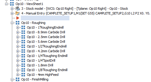
Finish Machining Post Hard Coat Type 3
in Industrial Forum
Posted
Cast is probably out. The part has been approved for production since 2020 with 6061 being specced by the customer. They can be a pain to get changes through and most of the time asking fewer questions is just easier.
I looked at the print again and to my surprise they don't specify what temper of 6061 they want. So maybe we could look into that?
Also, thanks for telling me it's a cold process. I'm pretty new to this anodize stuff since I only deal with it pre-plating. Now that they got me going after it post plating I am trying to find as much info as I can. I just recall (probably incorrectly) that when I first started here that someone told me we bake our parts since it helps stabilize them prior to anodize and that the temp we ran at was similar to the anodize process.