RecceDG
-
Posts
55 -
Joined
-
Last visited
-
Days Won
3
RecceDG's Achievements
")


-
 Is there a way to get Mastercam to show the lateral force at the tool and how much power is being used, at any given point in the toolpath? Thanks!
 -
Well it turns out that getting Mastercam to violate the right-hand rule is trickier than I thought, so I flipped my Y axis direction on the machine and got on with it.
-
To what effect? That corrects the jog handle numbers, but assuming the part zero remains "back left", now X coordinates "in the part" are positive, but Y coordinates are negative. With the orientation as per diagram, all XY "in the part" are positive.
-
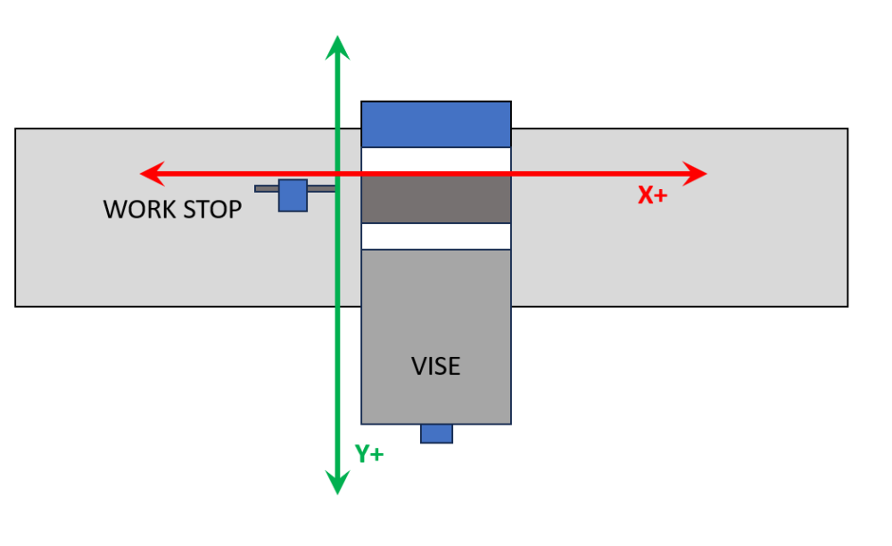
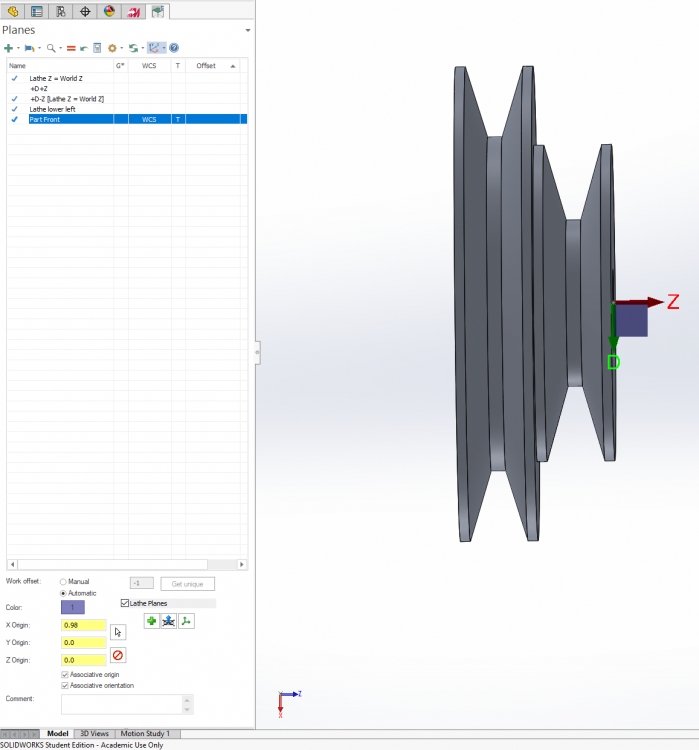
So I have finally gotten my mill conversion done to the point where I can actually start cutting metal! Huzzah! Up to this point, all my machine work has been on a lathe (which is its own deal) or on a gantry router. On the gantry router, X0 Y0 is left front of machine, and Z0 is set to either top of stock (my usual setup) or rarely, surface of table. I have a workstop installed that is a right-angled step on the table at a known XY. The work is pulled up tight against the stop then clamped down, so I only ever have to probe the stock top height. On the mill, that won't work, because the moving jaw of the vise is outboard where the inboard jaw is fixed. That suggests an axis orientation as per the attached diagram - and because I am master of my own domain as far as machine configuration goes, I can easily set that up. I presume I can tell Mastercam that part zero is upper left and Y increases coming out. Aside from this meaning two different axis orientations depending on if the part is router or mill - and that the numbers on the jog handle are backwards in Y - I can think of no downside to this. Thoughts?
-
Is it just me, or is Tool Manager kinda... lacking?
RecceDG replied to RecceDG's topic in Industrial Forum
Doesn't work. It applies blanket parameters by material with no tie back to the tool. It should be tool number AND material AND cut type, not tool number OR (material AND cut type). My tools have different flute counts, helix angle, rake angles - you can't just call them "carbide" or whatever. -
Is it just me, or is Tool Manager kinda... lacking?
RecceDG replied to RecceDG's topic in Industrial Forum
Well with Mastercam for Solidworks going away (!) I can see them wanting to improve the CAD side to make Mastercam more of a single-solution, where right now its more Solidworks for CAD and Mastercam for CAM. Which makes the tool management shortcomings more baffling. I get that Mastercam doesn't want to be tool inventory management, but you'd think there'd be an easy way to associate feeds & speeds, by material and cut type, to individual tools. -
I've just started XMas leave so I have 3 glorious weeks to play with tools, and the final parts for my CNC conversion of my bench mill came in, so I'm doing my homework and setting up Mastercam for use with the new machine. Part of that is setting up the tool library in Mastercam and Mach 4 and labeling assemblies. So I modeled my toolholders in Solidworks, exported them to STEP files, used Tool Manager to import them as holders. Then went through all my tools, created those. Then finally created assemblies using the definitions. T1 through T13, all GTG (I have a drill chuck, a shell mill, and an ER collet holder that I'll do later) So I have spent more than a couple of hours in Tool Manager learning how it works and setting up my tools. And... I'm a little underwhelmed by the granularity of the data it stores and the usefulness of the data relationships. Like, it has the ability to select "roughing", "finishing", or both, and set Ap and Ae as a percent of D... but not separate feeds and speeds for roughing and finishing. I can go into the stand-alone tool manager and define cut parameters and materials... but I can't tie them to either tools or assemblies? Changing the tool data doesn't update the related assembly? I should be able to, in tool manager, be able to say "when using this tool to rough slot 6061, Ap is 1D, Ae is 1D, SFM is 1000 and Fz is 0.003"/tooth. When rough shoulder cutting 6061, Ap is 3D, Ae is .5D, SFM is 1200 and Fz is 0.0035"/tooth" and so on - and then creating a new toolpath should pull these values from the tool DB. Specify cut data per tool, per material, per roughing/finishing, per slotting/shouldering/facing etc. Am I missing something? I feel like I have to start a notebook with a page per tool that records cut data, because Tool Manager can't do it. Am I wrong?
-
Arrrgh.... never mind. You just start typing the number and it enables text entry. I'll leave the thread up for the next dumbass to find.
-
With the CNC conversion of my bench mill nearing completion I'm doing my homework and creating my tool library of tools, holders, and assemblies. I've got most everything sussed out, save this: I see how to adjust tool stickout graphically by grabbing it in the interface and sliding along the linear scale, but I see no way to manually set that value. I can't just click on the numeric field and type it in. There's probably some n00b trick that I don't know about.... How do I do it? Thanks!
-
I feel like I'm missing something here, in that I'm not following the last couple of posts. So I'm going to do a part with a 2D pocket in it. Sketch stock X/Y extents in Solidworks, extrude up Z, sketch pocket on upper Z face, extrude cut down to depth. In this case I'm not doing a facing cut or anything, just the pocket, so stock extents are part extents. Go into the Mastercam tab, define stock extents as geometry extents, and I think I have to click on a corner to get the stock to line up with the geometry instead of being centered on it. I also have to pick a plane, so I use whatever plane gets me +Z as "up" (I think it is Mastercam Top, might be Mastercam Front) So now I have the gnomon on the left front (X/Y) corner where I want it, but Z0 is on the bottom of the part and I want it on the top. So Planes Manager, Add New Plane, From Geometry, pick the top face of the part, call it "Stock Top" and check WCS, T, and G. Now the gnomon is correctly located on the top face, left forward corner like I want. New Pocket operation. Select the bottom face in the pocket for geometry. MC generates a chain around the edge at the bottom of the pocket. Back to cut parameters. Fill in tool, speeds, feeds, roughing steps, yadda yadda. Preview cut and it's what I want. Post code. Examine code, and instead of Z values being negative (down from zero) they are positive (up from part base). Curse. Swear. Tear hair. Back to pocket parameters. Discover an option to pick WCS plane (why is this not inherited from planes manager?). Set WCS plane as "stock top". Regen code. Toolpath is identical. Post code, Z heights are negative, as expected. Nowhere did I mess with "depths", incremental or not. What did I miss?
-
OK, thanks. When I get home I'll see what I have set.
-
Can you post a screenshot so I can see what you mean?
-
Back to XCarve. I need to do a better job of setting up machine definitions so I can easily tell MC which machine I'm on - especially because I can go for months without using MC. I wound up using the default mill definition for this job which doesn't use my GRBL post processor, so I had to hand-edit a bunch of the gcode. This was a basic engrave job. Do the lettering in Adobe Illustrator, export as DXF, pull that into SW as a sketch, extruded cut, 2D flat mill out the pockets. Not a "vcarve" engrave job with a chamfer bit; a flat-bottom mill job. Mastercam refused to recognize the faces at the bottom of some of the letters as closed chains until I changed the chain tolerance from 0.0001" to 0.001". Not at all sure why. I prefer to have my work zero be the top of the stock, usually front left corner. One thing that Fusion does very well is it makes setting the WCS origin super easy as part of the stock definition. MC, I need a new plane, so go to Planes Manager, "Add New Plane", grab the geometry that is the top of the stock, name this plane "Stock Top", set it as WCS, G, and T. Display shows the gnomon in the right spot. ...but then the toolpaths are offset by 0.75" (the thickness of the stock), like the Z zero was the bottom of the stock. WTF? And that's when I find as option in the pocket operation to pick the zero plane... Set that to "stock top" and now everything works as expected. Why does this not reference the WCS plane in the plane manager? Why in the name of Lob does the pocket op have a separate plane select option? But I got my code exported and it cut fine, so huzzah!
-
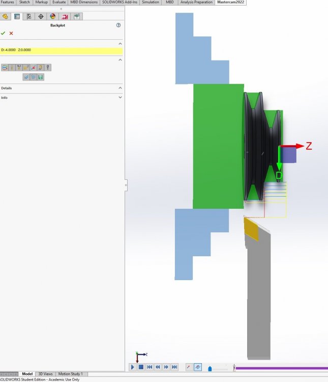
...and I just redid the tool, and the new version doesn't work - "unable to find intersections" - so I clearly missed a step somewhere. Here's my zero problem. Planes setup. Picked a plane on the part front. Set the offset. Gnomon is is correct position at the origin I want. But the toolpath uses the origin at the part base - the home position for the tool here is Z=0, which makes it easy to see. It's screwed up even before it gets into post - comes into MC in the wrong orientation (upside down). ...but that might be in the tool definition. I just redid it, and checked some different boxes to ensure left spindle/bottom turret, but now it doesn't like it at all.
-
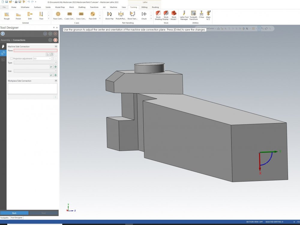
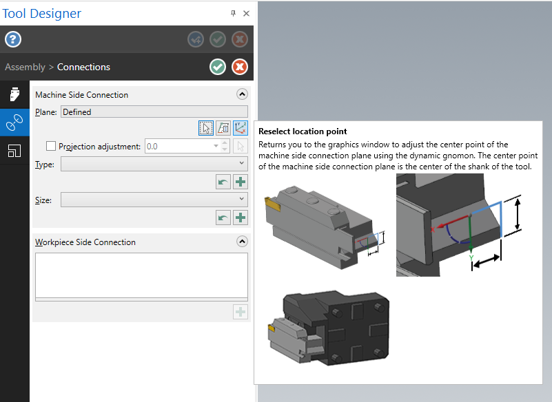
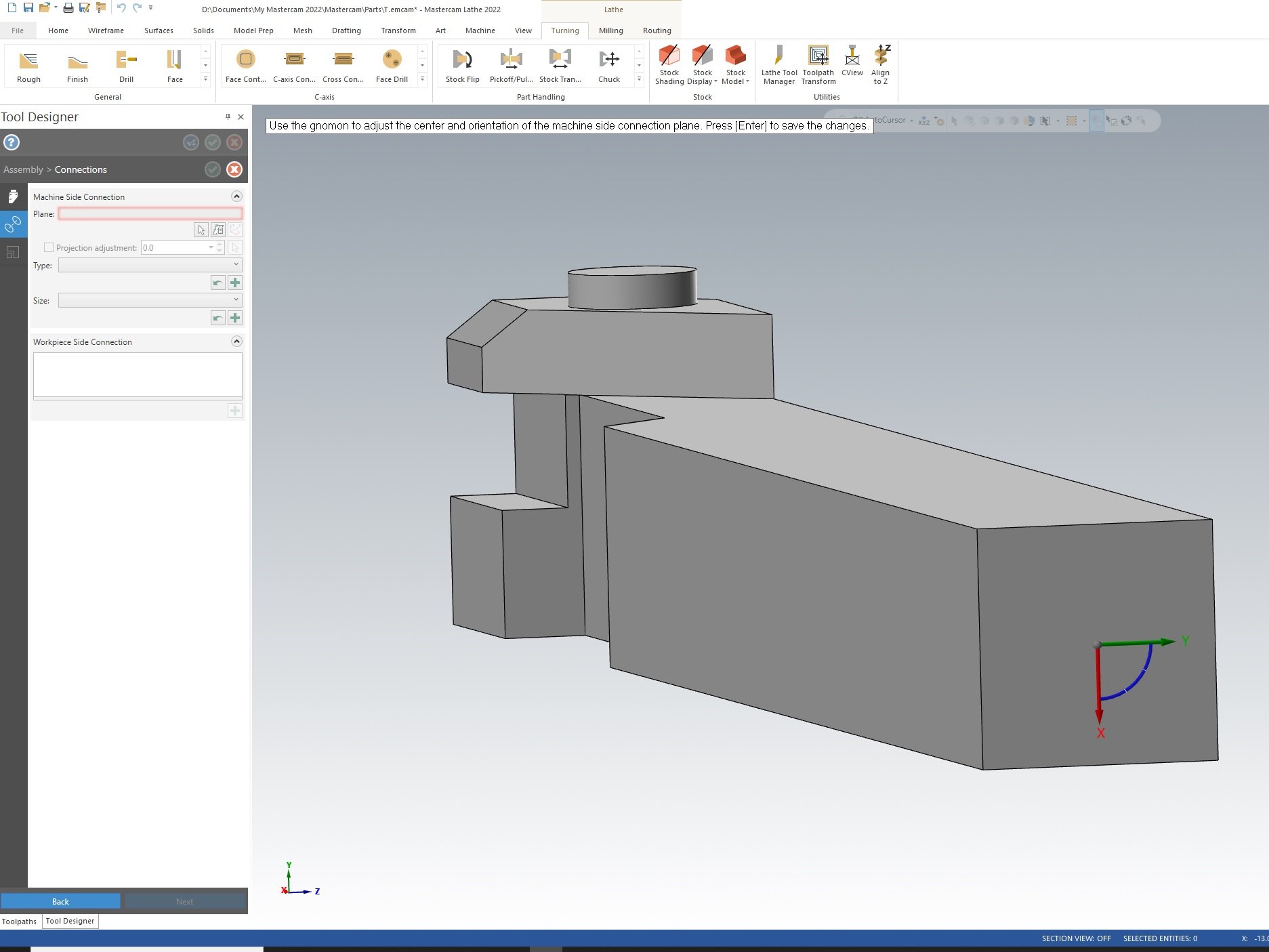
As I understand it, MC4SW is more-or-less standalone MC running in a SW instance, so all the UI elements, shortcut keys etc should be the same. But I have to use MC standalone to edit 3d tools, so that's moot. Anyway, here is an example. This is the holder for the tool in question. I rotated in in SW before exporting as STEP so that it would be oriented the same way in the machine - that is, the origin in the lower left is oriented the right way, with the long axis of the tool in X, Z+ going right, and Y+ going up. The lathe in question is a CNC converted bench lathe, not a slant lathe, so the spindle is left and the toolpost is on the near side. The screenshot shows the step where I define the machine connection. Now the tooltip shows the X left and the Y down, so I rotated it accordingly... but I do not understand why it wants THAT orientation - should it not match the lower-left axis orientation? Is there a way to change the dynamic gnomon (the one on the back of the tool) to control different axis?