


Digital_User
-
Posts
4 -
Joined
-
Last visited
Content Type
Profiles
Forums
Downloads
Store
eMastercam Wiki
Blogs
Gallery
Events
Posts posted by Digital_User
-
-
45 minutes ago, Chally72 said:
Mesh entities do come in with a normal, even if you can't display it in earlier Mastercam versions.
Even if you can't flip the normal directions, you can still simply change your tool axis control method or tool plane to force the tool to come from the opposite side, just as you can with surfaces:
Thank you all for your answers.
@Chally72 this is exactly what I'm searching for. Could you please explain how have you done this?
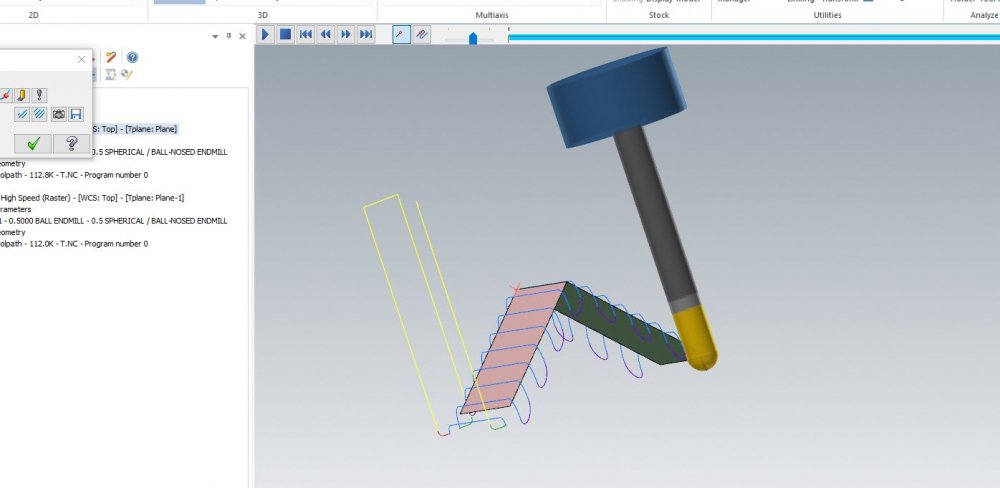
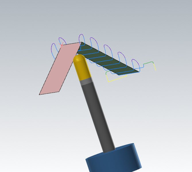
I've tried it for my own use case but it doesn't worked, as you can see in the following picture.

In the beginning of the sequence, the mill tool is in the correct plane (Left). But when the mill starts to machine the part, Mastercam is machine the wrong plane (Right). I added the Mastercam 2021 file and the part in the annex to make my problem more clear.
Thank you for your help.
-
On 8/14/2021 at 6:59 PM, Colin Gilchrist said:
Don't drive the Mesh > create a section of a Cylinder (Simple Ruled Surface), "underneath" the mesh.
Use the cylindrical surface as the "drive surface", and use the Normal to control which side of the surface you are cutting on.
Then use a "Collision Control" strategy, and make that Mesh object the "check surface" or "compensation surface", depending on which particular Toolpath you are using.
A simple "parallel" or "Morph" would give you control over "how the tool moves across the "drive surface", and then you can use the "Retract Tool, Along Tool Axis" Collision Control, to keep the tool tangent to the Mesh, instead of the cylinder.
Thank you all for your replies.
@Colin Gilchrist your idea is clever. But isn't there an easier way?
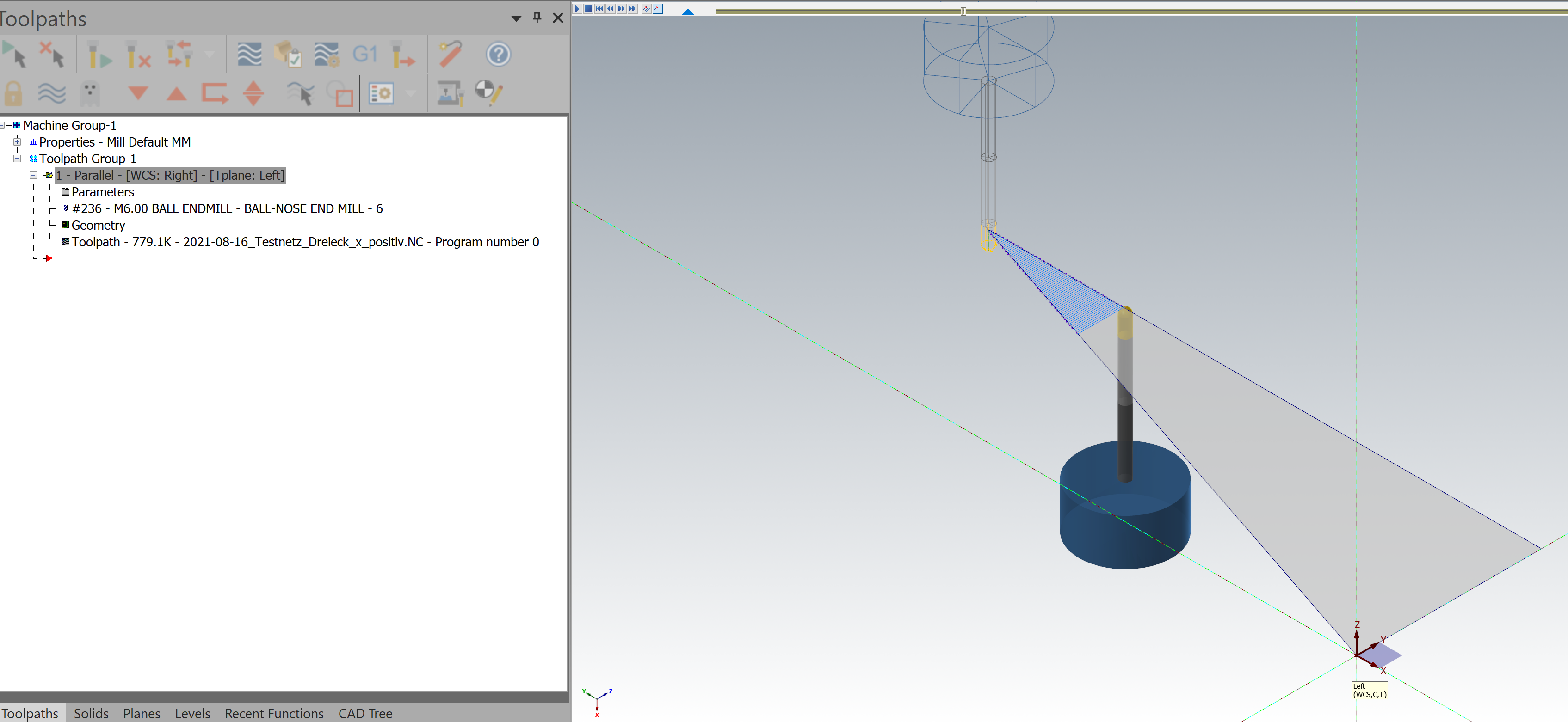
For instance, I have a simpler object like in the picture below.
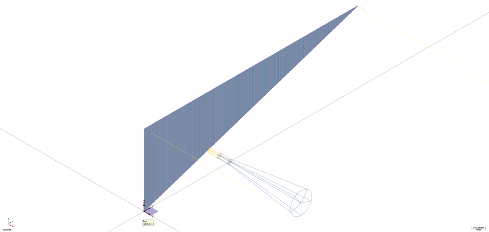
There is only one triangular mesh element with no thickness, imported as a step file. There is only the option in Mastercam 2021 to select the whole element, when I choose a mill machine and the multiaxis parallel toolpath.
Why is Mastercam choosing especially this surface to machine the part? Is there any option to "say" Mastercam to machine the opposite surface of the part?
I would appreciate your help.
-
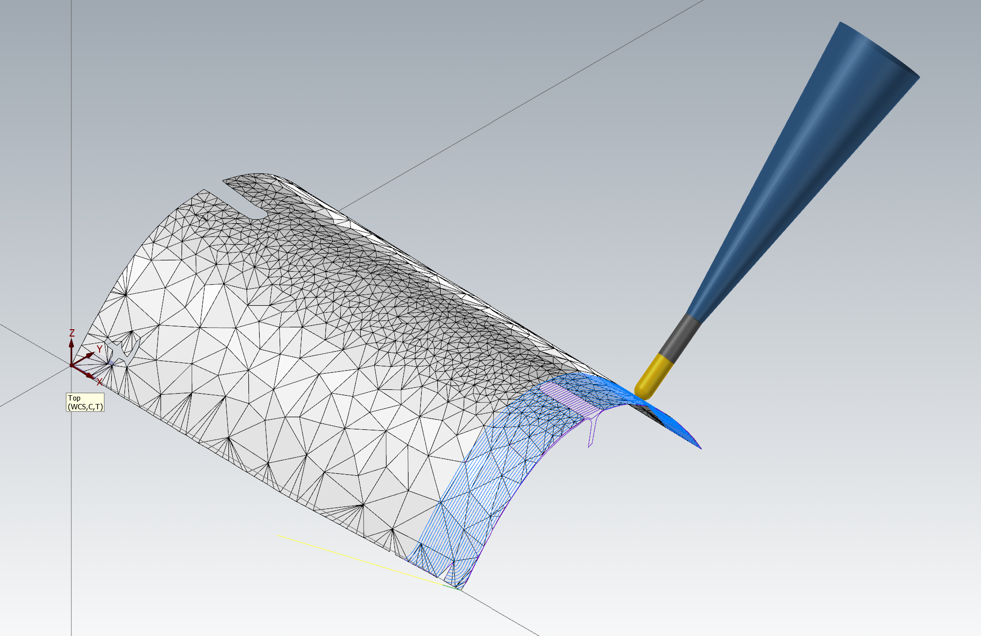
Hey people,
I'm trying to machine the inner surface of the cylindrical workpiece, shown in the picture. The workpiece is a converted step file from a originally stl file of a 3D scan. It has no thickness and includes only triangular mesh elements. So it isn't possible to select a inner and outer surface of a triangular element. It's only possible to select the whole triangular element.
The problem is that Mastercam 2021 automatically machine the outer surface of the workpiece, as you see in the picture, when I choose the multiaxis parallel toolpath and select all the elements.
I already tried to import the workpiece with a rotation of 180°, so the inner surface is at the top. I also tried to change the WCS, the CPlane and the TPlann, but nothing worked.
Is there any option to force Mastercam 2021 to machine the inner surface, i. e. to invert the tool axis about 180°?
I would appreciate your help.


Changing Tool Axis Orientation
in Industrial Forum
Posted
Hey everybody,
I've got the solution for my problem from my business partner.
There is an option to invert the normal of a surface. The result of this is that Mastercam will machine the inner surface of my cylindrical part.
Thank you all for your help.
All the best.