RON S
-
Posts
6 -
Joined
-
Last visited
Content Type
Profiles
Forums
Downloads
Store
eMastercam Wiki
Blogs
Gallery
Events
Everything posted by RON S
-
I am not sure what the file you are using looks like but the sample I posted in the original post was just a fairly simple box with some holes. X6 STL file size was 798K and the X6 LWN was 805K with .001 tolerance. The X7 STL file was 36,619K with a .002 STL tolerance which is over 45 times larger. If you are testing a completely surfaced part they will probably be closer because even X6 has tons of triangles to display a surfaced part. If you test a simple part with large flat faces I believe you will get a larger difference because X6 would only use a few triangles to display a flat face while X7 will use hundreds of triangles to display a flat face.
-
Wow this turned into a hot topic, I was begining to think I was the only one using STL's. Stock model is ok for simpler parts but I had problems in X6 with it leaving operations out of the model so I went back to STL's even for simple parts. I have not used it a lot in X7 yet so I don't know if they fixed it but I don't believe there is any way to save a stock model and be able to shift it and save it to use in another operation which we need to do for our 5 axis machines. I have programmed several complex 5 axis parts in X7 but it's definetly a struggle. I have played with the verify xml trying to find a happy medium but its either very ugly, very slow or ugly and slow. I haven't tried it but I am guesing I would need to use a .020 STL tolerance in X7 to get the same size file X6 saves with a .001 tolerance, but that model would not be good for much. The only thing that makes it even usable is having the verify in a seperate window. I even talked the boss in to buying a 3rd monitor so I can leave veify on all the time on its own monitor. This way you can do something else while its loading and running. I tried the Click to fix on the 5 axis part I am working on but it crashed several times because the file was to large. I will have to try the Meshlab but it sure would be nice if Mastercam would save an STL that you could use with out having to run it through another program. I will try and submit to QC. Maybe they will fix it in X10.
-
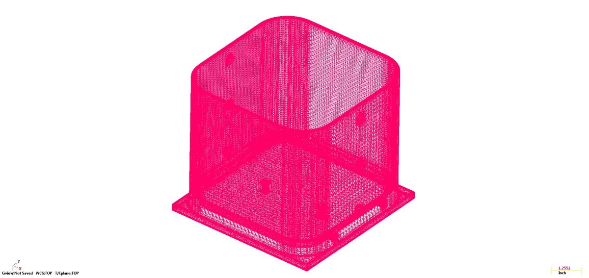
This may have been covered allready but you can't seach for STL on the forum because its to short. Is there any way to save an STL from a verify in X7 that is not such a huge file? We have been having trouble using the STL's from X7 verify so I did a little test on a simple part. The first picture is from X6 and is 798 KB using .001 tolerance. The second picture is form X7 and is 36,619 KB using .002 tolerance. Thats over 45X larger with twice the tolerance. We mainly use the STL's for our Matsuura MAM72-63V 5 axis 3 machine cell and have every op in a differnt file to make things cleaner and also our simulation/post processor (CAMplete) is built off C/L of rotation and ignors any WCS other than Top so we can't use multiple WSC's to program a muilti op 5 axis part complete if we wanted to so we save a STL at the end of the op and stl Xform to the new location for the next op. All this worked fine in all previous version of Mastercam but now X7 seams to have changed the way it saves STL's making them almost totally useless. I was able to import STL files into our simulation software for reference but know it just crashes because the files are too large. If any one knows of a solution I would love to hear it. Thanks, Ron Intel Core [email protected] Win 7 Pro 64 bit 32 GB RAM NVIDIA Quadro K4000 (3) 27" Asus monitors


-
I had this hapen when I was testing X7 on a file that had worked in X6. I found that the tip dia needs to be .0002 or larger to verify correctly. All my chamfer mills were difined as .0001 tip dia which worked fine in X6 but not in X7. Once I changed it they worked fine.
-
Any way to make 5 axis engine default in X7 verify
RON S replied to RON S's topic in Industrial Forum
Thanks, I was afraid that might be the case. Hopefully it will be fixed in the near future. -
Is there any way to make 5 axis engine the default in verify. Most of the work I do requires it plus the quality just looks better. Grouping a manual entry seems to set it to 5 axis but its just a work around. I have looked in the simulation xml and ini files and can't find where it sets the simulation engine. It might be faster then X6 to verify the hole part but it is way slower to verify just a couple operations especially if you have to go switch the engine and restart the simulation every time if you forget to group a manual entry. Thanks, Ron