


YoDoug®
-
Posts
1,309 -
Joined
-
Last visited
-
Days Won
45
Content Type
Profiles
Forums
Downloads
Store
eMastercam Wiki
Blogs
Gallery
Events
Posts posted by YoDoug®
-
-
I program and run an LT3000 every day. We just ordered an ABB IRB 4600 to automate it, should be here in 6 weeks. There are few things that I really like about the LT3000.
1. The thermal stability is awesome. I can start it up in the morning and the first part is in tolerance. Likewise, the machine sits very close to the overhead door that we bring material in and chip buckets out. In the winter that door opens and the shop temp drops by 10-20 degrees in a heartbeat. The machine stays stable.
2. The combination of the restart function and machine lock/CAS. I have my post almost perfect for our setup. I do not edit code at the machine. If I need to make a change I change it in TopSolid, repost and go. The machine lock and CAS functions allow me to run through the program quickly and safely to make sure we don't have any possible crashes. Then with the restart function I can restart easily at the right places for both turrets and finish the part.
3. The open API of the Okuma control. I have an app I made in C# that communicates with a Koyo PLC. The app watches certain signals in the machine like door open, in cycle, etc. Then it sets coils in the PLC to control chip conveyor, air knife on window, etc. The conveyor control is a big deal because the conveyor has an air knife to clear aluminum fines from the conveyor. The PLC minimizes the conveyor run time to only when needed so we are not wasting a lot of compressed air. I am working on adding a EIP output to the app for the robot cell. Our cell is designed to run multiple part numbers unattended. The machine tool is the master and will use the API app to pass variable info to the robot for part length, pick point, etc. This way we just use the machine schedule program functionality for production.
4. Lastly, but maybe most importantly is the ability for the NC to watch IO signal and make decisions. I have my post output a check at the beginning of each tool to check to see if the spindle that tool is working on is clamped. If it is not clamped it skips to the end of that tool. This allows me to run the same program for spindle 1 alone, spindle 2 alone, or both at the same time. It makes setup and prove out of new program very quick.
-
 3
3
-
-
5 minutes ago, danielm said:
Wish it wasnt an issue here. This project is a run off to meet or beat a cycle time. Right now we are 4 seconds over the time. Getting the taps to speeds alone would have us under the wire.
Have you seen the recent video that Okuma put together for cycletime reduction techniques in horizontals? Ask your distributor for a copy of it. It gives a few parameters and techniques that are not readily known. One is how to index the B axis while the machine is tool changing.
-
1
-
-
1 hour ago, danielm said:
We tried that Doug . No change. We're tapping a 5MX1 hole about 12mm deep. The tap feed starts as soon as the spindle starts and there just isn't enough time for it to get to speed before the tap is already at the bottom of the hole. RPM is 5000 and it only gets to about 3000. The problem is 2 fold...that tap can go faster and TMAC cannot monitor for tool breakage unless the spindle is idled out at RPM.
The spindle load hits 24HP as it ramps up. You'd think that the torque curve would be enough to get it to speed quicker. Must be the direct drive....not a geared spindle.
I'm not going to try to tweak the power parameters that the spindle control reads.....but I'm tempted.
That sounds about right from my experience. That is only 14-15 revolutions of the spindle to reach 3000 rpm. That is quite a bit of acceleration. The bigger the spindle and power, the bigger the mass . The result is slower ramp up time. Okuma's are actually one of the faster machines to go from 0 to full RPM. As far as Tmac, tap monitoring is different than regular monitoring. It requires you to set up a "time slice" of the tapping power to isolate between cutting and ramp up. If the spindle is ramping the whole way you may not be able to use TMAC.
-
On 4/24/2018 at 2:57 PM, danielm said:
Okuma MA4000B. OSP300MA control...
I'm trying to get tapping time down. The time for the spindle to get up to speed isn't complete before the hole is already tapped. Is there a variable anywhere to get the spindle to ramp up faster?
Thanks in advance.
DM
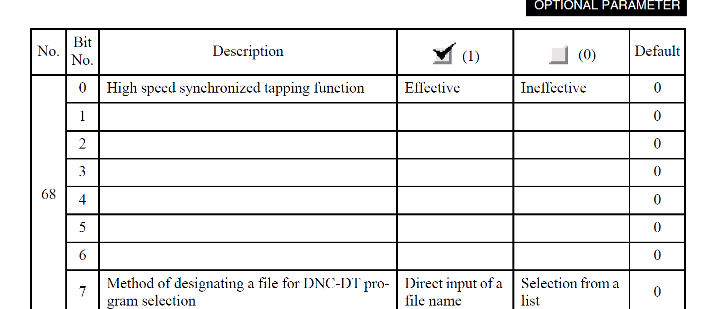
Make sure you have optional parameter 68 bit 0 checked. It is for high-speed sync tapping.

-
1
-
-
I think it is mostly used by 6 year olds.
-
 4
4
-
-
I run into this on a daily basis. I export from Topsolid and get the invalid stl error about 50% of the time. We also have Creo here and find about the same issue. One thing that does help is having the STL-eCheck lite program from Okuma on your PC. You can check the files before you go to the machine. I think it is still a free program. There is also a version that comes with the 3DVM software that will heal bad solids. That works every time, but it is not free.
-
 1
1
-
-
Here is another Okuma macro I just finished. It is for twin turret/twin spindle machines but could be modified for any lathe. It will save work offsets for A/B turrets, both spindles, and all 64 load monitor values for both turrets in a format that can be read back into NC to preload saved values into machine. It will create a file in MD1 called SETUP-SAVE.TXT. Just need to uncomment the turret calls, (G13) and (G14) to read as G13 and G14 in the TXT file before you copy it into your main program. Note; it takes about 3 minutes to write the TXT file since it is looping 128 times for load monitor values. For those that are cycle time concerned, it takes about 12 seconds to read in the data.
G13
G140
P1
(OUTPUT OFFSETS)CLOSE C
FWRITC MD1:SETUP-SAVE.TXT;C
PUT' '
WRITE CG140
PUT '(G13)'
WRITE C
PUT 'G140'
WRITE C
PUT 'P1'
WRITE C
PUT 'VSZOZ='
PUT VSZOZ,9
WRITE CPUT 'VSZOC='
PUT VSZOC,9
WRITE CPUT 'VSZOW='
PUT VSZOW,9
WRITE CG141
PUT 'G141'
WRITE C
PUT 'VSZOZ='
PUT VSZOZ,9
WRITE CPUT 'VSZOC='
PUT VSZOC,9
WRITE CG140
CONT=0
NSTRA
CONT=CONT+1PUT 'VLMB1['
PUT CONT,2
PUT ']='
PUT VLMB1[CONT],3
WRITE CPUT 'VLMB2['
PUT CONT,2
PUT ']='
PUT VLMB2[CONT],3
WRITE CPUT 'VLMBB['
PUT CONT,2
PUT ']='
PUT VLMBB[CONT],3
WRITE CPUT 'VLMC1['
PUT CONT,2
PUT ']='
PUT VLMC1[CONT],3
WRITE CPUT 'VLMC2['
PUT CONT,2
PUT ']='
PUT VLMC2[CONT],3
WRITE CPUT 'VLMCB['
PUT CONT,2
PUT ']='
PUT VLMCB[CONT],3
WRITE CPUT 'VLMM1['
PUT CONT,2
PUT ']='
PUT VLMM1[CONT],3
WRITE CPUT 'VLMM2['
PUT CONT,2
PUT ']='
PUT VLMM2[CONT],3
WRITE CPUT 'VLMMB['
PUT CONT,2
PUT ']='
PUT VLMMB[CONT],3
WRITE CPUT 'VLMS1['
PUT CONT,2
PUT ']='
PUT VLMS1[CONT],3
WRITE CPUT 'VLMS2['
PUT CONT,2
PUT ']='
PUT VLMS2[CONT],3
WRITE CPUT 'VLMSB['
PUT CONT,2
PUT ']='
PUT VLMSB[CONT],3
WRITE CPUT 'VLMX1['
PUT CONT,2
PUT ']='
PUT VLMX1[CONT],3
WRITE CPUT 'VLMX2['
PUT CONT,2
PUT ']='
PUT VLMX2[CONT],3
WRITE CPUT 'VLMXB['
PUT CONT,2
PUT ']='
PUT VLMXB[CONT],3
WRITE CPUT 'VLMD1['
PUT CONT,2
PUT ']='
PUT VLMD1[CONT],3
WRITE CPUT 'VLMD2['
PUT CONT,2
PUT ']='
PUT VLMD2[CONT],3
WRITE CPUT 'VLMDB['
PUT CONT,2
PUT ']='
PUT VLMDB[CONT],3
WRITE CPUT 'VLMZ1['
PUT CONT,2
PUT ']='
PUT VLMZ1[CONT],3
WRITE CPUT 'VLMZ2['
PUT CONT,2
PUT ']='
PUT VLMZ2[CONT],3
WRITE CPUT 'VLMZB['
PUT CONT,2
PUT ']='
PUT VLMZB[CONT],3
WRITE CG4 F.01
IF [CONT GT 63] GOTO NENA
GOTO NSTRA
NENAPUT 'P2'
WRITE C
PUT 'M331'
WRITE C
PUT 'G140'
WRITE C
PUT 'P-99'
WRITE C
CLOSE CP2
M331G14
G140
P2CLOSE C
FWRITC MD1:SETUP-SAVE.TXT;A
PUT' '
WRITE CPUT '(G14)'
WRITE C
PUT 'G140'
WRITE C
PUT 'P1'
WRITE C
PUT 'VSZOZ='
PUT VSZOZ,9
WRITE CPUT 'VSZOC='
PUT VSZOC,9
WRITE CPUT 'VSZOW='
PUT VSZOW,9
WRITE CG141
PUT 'G141'
WRITE C
PUT 'VSZOZ='
PUT VSZOZ,9
WRITE CPUT 'VSZOC='
PUT VSZOC,9
WRITE CG140
CONT=0
NSTRB
CONT=CONT+1PUT 'VLMB1['
PUT CONT,2
PUT ']='
PUT VLMB1[CONT],3
WRITE CPUT 'VLMB2['
PUT CONT,2
PUT ']='
PUT VLMB2[CONT],3
WRITE CPUT 'VLMBB['
PUT CONT,2
PUT ']='
PUT VLMBB[CONT],3
WRITE CPUT 'VLMC1['
PUT CONT,2
PUT ']='
PUT VLMC1[CONT],3
WRITE CPUT 'VLMC2['
PUT CONT,2
PUT ']='
PUT VLMC2[CONT],3
WRITE CPUT 'VLMCB['
PUT CONT,2
PUT ']='
PUT VLMCB[CONT],3
WRITE CPUT 'VLMM1['
PUT CONT,2
PUT ']='
PUT VLMM1[CONT],3
WRITE CPUT 'VLMM2['
PUT CONT,2
PUT ']='
PUT VLMM2[CONT],3
WRITE CPUT 'VLMMB['
PUT CONT,2
PUT ']='
PUT VLMMB[CONT],3
WRITE CPUT 'VLMS1['
PUT CONT,2
PUT ']='
PUT VLMS1[CONT],3
WRITE CPUT 'VLMS2['
PUT CONT,2
PUT ']='
PUT VLMS2[CONT],3
WRITE CPUT 'VLMSB['
PUT CONT,2
PUT ']='
PUT VLMSB[CONT],3
WRITE CPUT 'VLMX1['
PUT CONT,2
PUT ']='
PUT VLMX1[CONT],3
WRITE CPUT 'VLMX2['
PUT CONT,2
PUT ']='
PUT VLMX2[CONT],3
WRITE CPUT 'VLMXB['
PUT CONT,2
PUT ']='
PUT VLMXB[CONT],3
WRITE CPUT 'VLMD1['
PUT CONT,2
PUT ']='
PUT VLMD1[CONT],3
WRITE CPUT 'VLMD2['
PUT CONT,2
PUT ']='
PUT VLMD2[CONT],3
WRITE CPUT 'VLMDB['
PUT CONT,2
PUT ']='
PUT VLMDB[CONT],3
WRITE CPUT 'VLMZ1['
PUT CONT,2
PUT ']='
PUT VLMZ1[CONT],3
WRITE CPUT 'VLMZ2['
PUT CONT,2
PUT ']='
PUT VLMZ2[CONT],3
WRITE CPUT 'VLMZB['
PUT CONT,2
PUT ']='
PUT VLMZB[CONT],3
WRITE CG4 F.01
IF [CONT GT 63] GOTO NENB
GOTO NSTRB
NENBPUT 'P2'
WRITE C
PUT 'M331'
WRITE C
PUT 'P-99'
WRITE C
CLOSE CM30
-
4
-
-
44 minutes ago, huskermcdoogle said:
You mention small batch sizes and small parts. Can you define run times per part and how many you are looking to do per order? Two to ten parts per face means they range from medium in size to small in size. Are you looking to run single piece flow or are you wanting to gang up multiples of each part? Maybe there is a far cheaper long term solution. Don't get me wrong, I love me some 500mm Horizontal action, especially with a pallet system hooked up to them, but they are a lot of coin for one spindle, and even more coin to tool up. But if the goal is to have one operator running it on one shift, and it runs through the night every night unattended, then well, it's probably the right way to go. But you knew that already. So I'll get off my soap box. But depending on mix and required volumes, have you considered maybe something like a methods job shop cell? Given the right zero point fixture setup, there isn't much reason you can't change fixtures with the robot as well, which could extend your unattended time significantly.
Of the 150-ish part numbers our 3 month part usages range from 10 to 200 pieces. Everyday we need to flexibly change schedule to run small batches of parts. We looked at smaller pallet systems in verticals and/or robots, but after all the number crunching the Horizontal works out to be the best.
-
1
-
-
6 minutes ago, specv said:
Doug, You know my vote would be the Makino, even though we just bought the Kitamura's. The major reason we didn't buy Makino's last time was the limit in x stroke. With small parts the a61 should be good for you, I would look at the tall column though, it just gives you more y stoke if you are loading up a tombstone with parts.
Definitely looking at the tall column as well as heavy load capacity. We are looking at having 8 sided tombstones with 2-10 parts per face depending on part size.
-
Hello Mastercam peeps. At my new job we are spec'ing out a new 500mm horizontal. Since I am no longer bound to Okuma by employment I am looking at Mori and Makino in addition to Okuma. We have roughly 150 different part numbers that need to be set up for small batch production so we are looking at 10-20 pallet systems. The parts are all very similar and share common tooling so 60 ATC will handle all of our needs. All aluminum parts but no really small tools so 15k rpm should be adequate. I am looking for any opinions and experience with the following machines.
Makino A61NX W/pallet system
Mori NHX5000 2nd gen W/pallet system
-
4 hours ago, Maclaw said:
But unfortunately when I use scheduled progs the machine doesnt display the program flow... And this is an issue in my company. It's against our internal safety procedures - how can an operator run a program "in blind"??? This is some kind of absurd....!!
When you are in a schedule program there is a soft key that allows you to toggle between display of running program, schedule program, or sub program. You don't have to run blind.
-
10 hours ago, Colin Gilchrist said:
The best setups I've seen use Air Knifes, placed as you would "chip wash down" sprayers. This was on a system cutting Ti, that was using Liquid Nitrogen - Thru Spindle. It was on a Mill-Turn machine, VTL-style. They chose the Liquid Nitrogen because it leaves zero residue on the parts, and allows almost double the SFM compared to flood coolant at 12%. In addition, when turning on this machine, with LN directed at the turning insert tip, the chip control is fantastic. Even in materials that tend to be stringy, with poor chip breaking control (rat's nest), the combination of high heat generated in the cutting zone (800-1000 SFM in 6AL-4V), and the rapid transition to far below freezing, gives you chips that break quickly and consistently.
So the secret to running without coolant is using compressed air to push the chips into the chip trough.
For anyone considering LN, just remember that you should run a ducted fan to the outside of the building to vent the machine's enclosure. Also, it is wise to let the system stop pumping LN for a couple minutes before you enter the workspace. The nitrogen is already 78% of the air you breath, so it is harmless, unless it happens to displace the 21% of atmospheric oxygen, which could technically make you pass out and kill you. But with the proper care, it is a much better system than using liquid coolant.
I have seen an air knife tried for aluminum that was a catastrophic failure. In order to get the chips not to pile in the corners the air pressure had to turned up to the point that the light aluminum chips were flying around the machine like a debris in a hurricane. Then when the air was turned off they all fell back to the corners. Maybe more strategic placement of air would help solve that problem but, compressed air is not cheap. The cost of all that air would be crazy expensive just to be able to machine dry.
-
16 hours ago, bushpiolt said:
What Robot are you going with? I see there is software out there for Robots as well have been curious how well they work, seem to be in the early stages....
We are probably going to go with Kuka for robots. They seem to be the easiest to integrate a six axis force sensor for polishing.
-
1
-
-
I would love the idea of dry cutting but the question I have is chip management. I'm working on a project right now in a twin turret, twin spindle lathe making aluminum parts that require super fine finishes. the parts are to be loaded and run unattended by robot. Without 1000psi coolant I couldn't imagine how this could be accomplished. The chips build up so fast. We are also setting up mill parts that require the same finishes and have a lot of material removal. If we didn't have all the coolant wash down we would have to have and operator there constantly blowing chips from the sides of the machines into the augers.
-
1
-
-
5 hours ago, Colin Gilchrist said:
This Post was written in 1994, and was last updated in 1995.
Rockin' the vintage post! Ready Player One!
-
1
-
1
-
-
There are four different versions of NAVI.
1. NAVI Mg - this is a guided version for the mill. It uses a microphone and other input from user to minimize chatter. It is more of a manual operation.
2. NAVI Mi - This is an automatic version for milling spindles that uses a vibration sensor to analyze chatter and adjust speeds automatically.
3. NAVI Lg - This is a guided version for lathe turning operations. This is used in conjunction with the spindle speed variation function to minimize chatter.
4. NAVI Tg - This is a guided version for lathe threading operations.
The NAVI-Mi is really impressive. We have a customer with a Multus U3000 that has the NAVI-Mi. They were using a 1/4 inch end mill sticking out about 1.75 inch to mill down inside a pocket on a part. The programmer set the initial speed at 6000 RPM. The endmill was chattering and the finish was poor. The operator reduced the speed to 3500 RPM to get a good finish but the cycle was slower. we helped them set up the NAVI Mi and it bumped the speed to 6014 RPM's and the finish was great with much shorter time in cut. The software shows you real time signals from the vibration sensor in both time domain and frequency domain. You can zero in on the unwanted frequency components and minimize them to improve cutting performance.
-
2
-
-
My experience is that you just add a P1 to your G43.4 TCP call line to turn on tool posture control. There are some parameters that dictate how much angle deviation it will allow before it corrects the posture.
-
1
-
-
This website will let you type or copy/paste text and convert it into a QR code. Then you can download a JPG of your QR to put on your setup sheet. Then any simple QR reader phone app can read it. I used it recently to create QR codes for setup info on a fixture. Then we laser marked the QR code onto the fixture.
http://www.barcode-generator.org/
-
2 hours ago, Chris Kozell said:
Guys, my name is Chris Kozell and I work for CNC Software(Mastercam). I work out of the Partners In Thinc in Charlotte NC with Okuma America. The Multus U post in the Mastercam MT should work great with no post edits unless you are trying to do something wonky. I use that machine environment alot and have received awesome feedback from end users that the post functions very good. If you are having to make edits please, please contact your reseller and have them check to make sure you are running the latest version. If not, dont hesitate to contact me. Thanks for your support!
Please don't take my comments as criticism but we are a machine tool distributor that gets our licenses and support directly from CNC software. We have requested updated posts and tried to help get changes implemented. We have not had very good response to our requests.
-
21 hours ago, bushpiolt said:
Hows their post??? For say Okuma Multus??? Any hand edits needed?
The Multus post is still being tweaked. It is close though. Honestly though, I have Mastercam MT, Esprit, and TopSolid on my PC. None of them can post 100% for the Multus U series. I have cases for all that still require hand editing, even with the "certified posts".
-
1
-
-
On 11/17/2017 at 9:10 AM, PKMills said:
Thanks for the info YoDoug! I may give that a try if I can't find a more simple solution since I'm somewhat of a newbe when it comes to Okumas and part probing in the machine. I wanted to use Okuma language if possible. I know there is a 3 point bore gauging function but I can't find the PMOD and related variables in the manual I have.
The issue you are going to have with the standard Okuma measure cycles is that they only work in a single axis move. You will need to do your own G31 skip move and record the location of hit. You can do what you are looking for but it will take a bit of macro writing to get there. Your best bet is to use The Renishaw O9823, three point cycle to get the measurement you are looking for. If you don't have the Renishaw inspection plus macros I would recommend buying them. You will spend more time and cost trying to write your own macros than you can buy the Renishaw macros for.
-
3
-
 1
1
-
-
On 11/16/2017 at 4:27 PM, nickbe10 said:
Can you do arithmetic functions imbedded in the macro to do the calculation in Okuma speak ?
RAD=SQRT[[XP1-XCEN]*[XP1-XCEN]+[YP1-YCEN]*[YP1-YCEN]]
-
1
-
1
-
-
Use Mastercam to figure out probe vectors for the three points on the radius. Make single point probe hits and record the three XY points to variables. Then the following code will find the center of a circle in Y and Z from three known points. Modify for X Y as needed.
OCIRC(CIRCLE THROUGH 3 POINTS MACRO)

YP1=VC31 (1ST Y)
ZP1=VC32 (1ST Z)
YP2=VC33 (2ND Y)
ZP2=VC34 (2ND Z)
YP3=VC35 (3RD Y)
ZP3=VC36 (3RD Z)

(GET PERPENDICULAR BISECTOR OF YP1, ZP1 and YP2, ZP2)
PRP1 = [YP2 + YP1] / 2
PRP2 = [ZP2 + ZP1] / 2
PRP3 = YP2 - YP1
PRP4 = -[ZP2 - ZP1]

(GET PERPENDICULAR BISECTOR OF YP2, ZP2 and YP3, ZP3)
PRP5 = [YP3 + YP2] / 2
PRP6 = [ZP3 + ZP2]/ 2
PRP7 = YP3 - YP2
PRP8 = -[ZP3 - ZP2]

(SEE WHERE THE LINE INTERSECT)
(Y-CENTRE)
YCEN = [PRP2 * PRP4 * PRP8 + PRP5 * PRP4 * PRP7 - PRP1 * PRP3 * PRP8 - PRP6 * PRP4 * PRP8] / [PRP4 * PRP7 - PRP3 * PRP8]

(Z-CENTRE)
ZCEN = [YCEN - PRP1] * PRP3 / PRP4 + PRP2

M02
After you know the center you can use Pythagorean theorem to find the radius from the delta between center and one of the original points.
Or you could do it the easy way and use Renishaw inspection plus O9823 cycle.
-
3
-
1
-
-
17 hours ago, heavychevy2155 said:
I'm so happy you are loving TS, as for us, we struggle every day with it to get usable code. Maybe it's just the way we have implemented it, but dear god!! I "bash it" because all of the great things they say it does, but it just doesn't really work for us. It seems every time there is an update our Okuma machine deff's get hosed and then we have to wait for Jay to do his magic song and dance. It also takes so much work just to be able to start programming. Import models, convert models, heal models, create Machine Part Setup, create a Machining. Then work on placing the MPS on the machine, maybe you can start programming at this time. Nope, machine element activation. Oh man I forgot to do a machine part environment, ok, got that done. So lets start putting down some toolpath, I'll do a sidemill toolpath, you think everything is looking good but your path goes everywhere but where you want!! Ok, Cad mode, then start sketching wire frame. WHAT!! you can't put wire frame on all edges, ok I'll just have to manually sketch it then. By the time I have to do all that crap, I would be half done with the job in Mastercam!! A day latter you finish programming this easy part, then lets do some setup sheets. Right click on Machining file, drafting, I'll choose tool sheet, operation sheet, fixture sheet, ok. Crap!! I forgot to publish my machine part environment and my machine part, might as well publish my origin point. Then spend half a day scaling all the models and tools so they are not all jacked up!!
As you can see, you have so much work up front to do before you can start putting down toolpath. Speaking of toolpaths, there really isn't any rhyme or reason to the toolpath setting's. The naming of the functions are just weird, and are buried in tab after tab. You get a toolpath to work then copy and paste it then you can't get it to work on the new geometry. So I'll just delete it and start with a new path and mess with it till it works. Hope you don't have to build a custom tool assembly, that is a battle I don't wish on anyone, You have to add all the frames and inherited functions manually and add revolution silhouette's for the tool and holder, add tool and ground groups with the functions added in.
As I have said, I am happy it works for you. I guess I'm just not as smart as the rest of the folks that say they love it. I'm ok with that, but I can and will "bash it" if I feel like it. Don't like it when I do, so what, I really don't care. All I see is the very large sums of money that we continue to throw at this software and get sub par results, but I'm just a lowly programmer with no say or pull within the company, but if I had to run a business with TS I can't see how you could keep the doors open with the short lead times that most manufactures demand these day. I could go on, but I'm tired of beating this dead horse.
I am in the loving TopSolid camp, but with that being said I will acknowledge that it is more laborious for simple stuff. If I only had to deal with single turret/single spindle lathes I would not like it. However, for complex twin/triple turret machines and five axis mills I love it. Although I can model all of BMT blocks for a simple Y axis lathe and accurately simulate multiple tools mounted in one turret station. As far as getting good code, I have never been afraid to edit when needed but I will admit the posts are like 90% there. I am hoping to take the post class with Jay sometime next year. For the things that do not post as it should, I make a lot of macros to handle repetitive things like spindle transfers, etc. As for Okuma machine def's, I make most of my own my self so they only update when I update them. I also use TopSolid for all of my modelling needs. I like having it all in one.
-
1
-
New Lathe Machine
in Machining, Tools, Cutting & Probing
Posted
I use TopSolid to program our LT3000, but I do know from my last job that Mastercam does have a decent MT post and simulation for the LT2000.