Roger
-
Posts
502 -
Joined
-
Last visited
-
Days Won
1
Content Type
Profiles
Forums
Downloads
Store
eMastercam Wiki
Blogs
Gallery
Events
Posts posted by Roger
-
-
On 5/3/2019 at 6:32 AM, Pete Rimkus from CNC Software Inc. said:
As far as I know, we still do not have the ability to import the result of those cuts when bringing the SLDASM into Mastercam. This has been a known issue for a while and is do to a technical limitation in the libraries SW provides for importing their native files.
Yes - if its exported to Parasolid (.X_T or .X_B) they'll come across to Mastercam, but not from the .SLDASM.
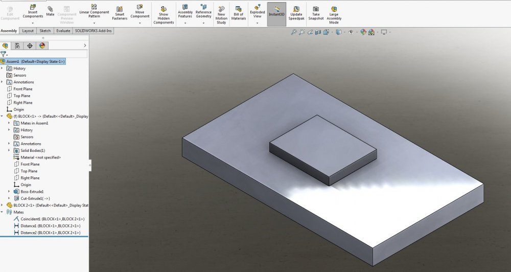
Maybe I'm not understanding the question. Please see attached Mastercam file where I built the base piece in Solidworks, built the block 2 in Solidworks, I then did an assembly in Solidworks by laying block 2 on block 1, edited block 1 in the assembly file by doing an extruded cut, using block 2 and converting the edges. Saved as an Solidworks assembly, and opened in Mastercam.
-
3 minutes ago, MSL said:
I use point toolpath when I'm knurling on cnc lathe.
Thanks! That's how I've done it in the past.
-
1 hour ago, heavychevy2155 said:
These will make your life so much better. I've used the CNC Modular System and it is so worth the money!! They come with recommended speed and feed chart for different dia.
and materials.
Are you talking about the cutting style, verses the forming style? What tool path do you use when programing your knurling? How do you touch off the tool? Can you share a MC file where you did knurling?
Also, thanks for the advice!!!!
-
I've did some knurling over the years, and it's always been a trial & error method. Any EXPERTS out there? Or, any good resources with feed, speeds, etc. My part is .75 diameter, 304 Stainless steel, with a medium knurl call out over a 1" length. The knurling tool is .315" wide, so I will have to feed it along the part.
-
44 minutes ago, Old_Bear said:
Unless something has fairly recently changed, Mastercam doesn't have the ability to read in features created at the assembly level.
I beg to differ with you. I make my fixtures by laying the parts on top of the material and converting entities, and doing the cutting in the assemblies..........And the whole assembly opens fine in Mastercam.

-
 1
1
-
-
20 hours ago, Colin Gilchrist said:
Hi Roger,
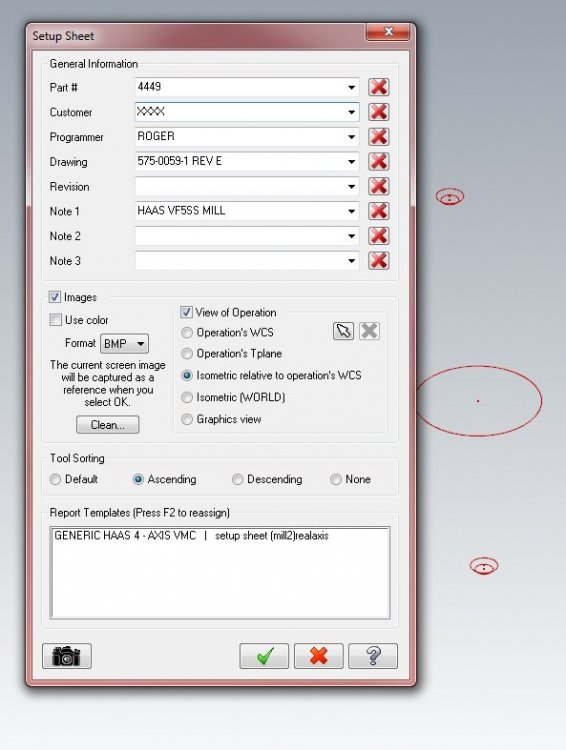
On that Dialog Box, there is a "Clean" button. That should remove old pictures of other jobs.
Thanks Colin!!! My old eyes have never noticed that.

By the way, we are still wanting you to come in. We still haven't slowed down enough to have time for you to come in. I hope you and your family are enjoying the move, have a Happy Easter!!
-
This is my settings. Maybe it got changed by accident. What setting would make it act like I described????
-
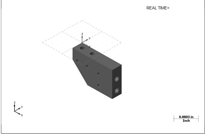
Yesterday when trying to print my set up sheet Mastercam was showing the WRONG screen shot! (See attached). I closed MC twice, same thing each time. I had to do a restart on the computer!!!!!!!!!!!
1st picture is the part I was working on. 2nd picture is the part I was previously working on..............
Anyone else ever have this happen? I'm using MC 2019

-
20 minutes ago, gcode said:
When you get into deep grooves, you have to buy a groove tool holder with a curved anvil that supports the insert
The tool will have min/max groove diameters it can cut.
When you have this kind of issue, you need to properly set the Face groove fields.
In this screen shot I was using a topnotch groove tool and these settings were unnecessary so they remain at the default setting.
When applicable, you use these fields to restrain the first cut to a diameter the tool can cut without wrecking the anvil
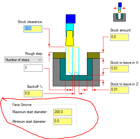
All this time I've been doing A LOT of face grooving, and NEVER noticed this box.............
 Thanks for the tip!!!
-
10 minutes ago, #Rekd™ said:
Sure looks like a flange from an Ultra-High Vacuum chamber?
Good guess!!!! Sorry, no prize awarded...........
Thanks everyone for your help! Contour seems to work.
-
1
-
 1
1
-
-
It now starts at the top, but does some really wacky moves 1st!!!
-
Currently regenerating......................LOL!!!!!!!!!
-
master80, what causes it to rapid down to Z-.308 instead of starting at the top? I've never used the surface finish tool path on this type of feature.........
-
I got help here on the forum 2-3 years ago on doing this. That part only had 1 hole at a 4 degree angle.
This new part has 4 holes at 18 degree angle!!! The attached file has the imported tool path from the previous part. (still needs regenerated). If someone is willing to look at this and give suggestions on what tool paths they would use, (If not the surface finish flowline), I would be very grateful.
-
Josh, FANTASTIC!!! Your video was an EXCELLENT WAY OF SHOWING ME!!! THANKS!!!!
-
1
-
-
Can this chamfer be made without surfacing on a 3 axis mill? All ideas appreciated. Or should I tell the customer it's not possible.............
-
Who else has a customer that is a real pain in the arse? Like changes the part after you already have it done! Gives you a print that's different from the solid model!! Makes revision changes, but doesn't list what they changed! AND THEY KEEP WANTING TO KNOW WHY THEIR PARTS ARN'T DONE..............
THIS IS ME RIGHT NOW!


-
I want to thank everyone for their suggestions. I ended up just typing it out longhand, copy, paste, (see attached NC code), because of time constraints.
When things slow down here I've reached out to Colin Gilchrist to come to our shop and do some post mod's, set up probing in Mastercam, etc. I hope he is still interested in doing this when that time comes.

I only have 15 of these parts to run, and everything looks good!
-
1
-
-
I need to drill some long holes (.256" diameter by 4.11" deep ), in aluminum, using a thru coolant 15 X solid carbide thru coolant drill. The recommend feeds and speed are 300 SFM, .004 IPR.
Here is my problem... It's been recommended that I use a chip break cycle (G73), and that a do a pilot hole 1st. How do I code this to feed down into the pilot hole at a slower RPM, ramp up the RPM's, etc...............
This is on a Haas mill. I'm using the generic Haas post. Is there a switch in the post to use custom drill cycles, and would I have to "make up a custom drill cycle"???
-
BUMP! I'm still looking for the answer to this question also! Anyone??
-
3 minutes ago, KLP1190 said:
I use Solidworks to handle most of my modeling
You can do surfaces in Solidworks.............
-
1 hour ago, SlaveCam said:
I would likely switch jobs if I couldn't design fixtures with Solidworks any longer.
I agree with you on that one!!!! Solidworks user here!!
-
1
-
-
Go to (Computer-OS (C drive)-Program files Mcam 2018- common-editors CIMCOEDIT
Right click on CIMCOedit, and click on send to, desktop (create shortcut).

-
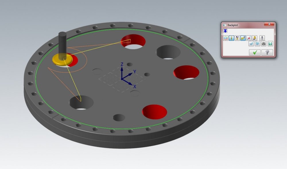
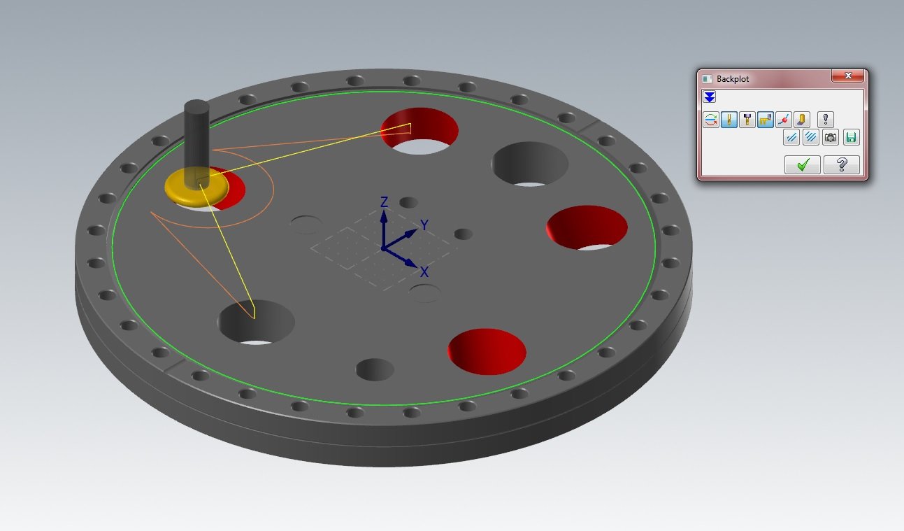
7 minutes ago, Chally72 said:
No, the way that button works is, if you click 'Save', it will save out whatever is currently displayed in backplot as geometry. So, if you pulled your backplot timeline slider halfway through the op and hit save, it saves out the displayed first half of the op as lines/arcs/etc onto a level. It's not a modal button that stays on- you just have the option to save off what is displayed whenever you want, every time you go into backplot.
There are some really neat 5axis tricks you can do with this button and combining it with the use of 'restrict drawing' buttons in backplot, and displaying vector lines through the backplot interface, that let you create very slick "From" drive splines for 5axis paths, for example.
Thanks!! That is nice to know! I still don't know how it drew it on the screen, because I've NEVER used it before.
I just deleted the lines, and I'm continuing with my "mission"
 Merry Christmas!!


Problems Opening a Solidworks Assembly
in Industrial Forum
Posted
Here is a screen shot from the Solidworks assembly file showing the history tree.