


Colin Gilchrist
-
Posts
7,781 -
Joined
-
Last visited
-
Days Won
164
Content Type
Profiles
Forums
Downloads
Store
eMastercam Wiki
Blogs
Gallery
Events
Posts posted by Colin Gilchrist
-
-
For the UMC machines, you "set" the G53 Z0 position at the Tool Change Height. Several of the Haas machines have travel "above" Z0. Typically, somewhere between 2.5-4.5" inches. This is not true for all Haas machines. Sometimes "G53 Z0" is the maximum travel height on the Z-Axis.
For machines where there is travel above the machine Z0. position, I modify my Post Processors to output G00 G90 G53 Zxxx, where the Z is the highest position you can jog to.
For example, the last UMC-750 I ran had a max Z Position of Z2.5311.
-
 1
1
-
-
Yep, Post Debugger, and you need a Mastercam License to use/run this.
Also, you can install and use Mastercam Code Expert, which has all the pre-defined variables and functions listed, using an "auto-complete" feature.
By the way, if you're looking to learn about Post Processors, I have a free Post Processor Class (actually several) on my YouTube Channel. Link in my Signature.
For MP 101 - Basic Post Processing, there are 28 videos. Be sure to watch all the Office Hours sessions as well.
For MP 301 - 5-Axis Post Processing, there are 20 videos.
-
1
-
 3
3
-
-
FYI,
If you've got the Multi-Threading Manager open, with no threads active, this enables a "configuration" button (looks like an exclamation point > !).
You can then set the "Default Thread Priority" to High, instead of needing to remember to set it on each thread.
Also, are you Filtering each-and-every Operation? Because if you're not (assuming they are also non-vector based), then you're missing out on both shorter NC Programs, and decreased processing time for Verify and/or Stock Models.
-
1
-
-
Having a single Stock Model, at the end of your process, means you single-thread the removal of stock, from start to finish. Because each subsequent operation is dependent on the removal of material from the previous operation, you're limited in the speed the operation can execute at.
Jake gave three great suggestions on how to potentially solve this issue. Or, just hit regenerate, and go get a cup of coffee while you wait.
If you pause the operation, you can also Right-Click and set the Processor Priority flag. I like to use "High". I've seen no difference between High and Real-Time, but High does seem to give a performance boost versus standard.
-
4
-
-
Leon is correct. Without access to the encrypted portion of the Post, you're not going to get TCPC on a Haas Post to work correctly.
One of the problems if you don't use the encrypted section of the Post > you won't be able to take advantage of the Misc. Values which give you control over the Posted code. For example > using Misc. Integer #10 to force the secondary (tilt) to either positive or negative, so you can keep the rotary on the correct (operator) side when needed. All the Safe Z Retract and or "Approach/Retract To/From Limits" code in the Post requires you use the encrypted section, and so on.
Also, having features like the ability to "read a T/C Plane which has the same orientation for the Z vector as the WCS", but using the XY vector angles to allow you to "clock" a part, so you can overcome travel limitations of the machine, these are all things you need access to the encrypted section to control.
-
1 hour ago, huskermcdoogle said:
Well, I guess I'll chime in here a little bit. For the question of if you can activate G43.4 H## without a z on a Fanuc 31i, absolutely. Do it every day. Not sure on our parameter setup, but there is no movement, but the absolute coordinates jump. But we are on a head head machine. Shouldn't make much difference going to a table table design, actually it likely makes it a bit easier.
99% of the time, unless I am up against a barrier, our format is:
G5.1 Q1 R#
G54
G43.4 H
G0 G90 X# Y#Z# B# C# S# M3
Basically speaking, I don't see any reason whatsoever if the machine doesn't move calling G43.4 H by itself in the current config. If the coordinates shift when you execute that line, and it doesn't move, it is configured not to. Then you can go about business as usual.
Now on another note, and I am by no means an expert on Table/Table machines, but why would one preposition with G68.2 then cancel and run TCP instead? Seems confusing and cluttery. In the example above using G68/G53.1, the post has already calculated and moved to the desired table angles, why call it again? Is it just to make the machine and post are in agreement before you put a tool to the part?
Anyway. Someday I hope to spend enough time on a table/table machines to understand some of these practices. I have spent ooodles of time tinkering with approach and retract code on the head/head configs, and head/head/table (with TCP on head but not table), and if I had motivation, have notes of thoughts on post structures and methods that would be HUGELY useful for readability and general simplicity of adjustment at the control if one were focusing on short run work. For the long run stuff it doesn't matter as much because you don't mind going back to CAM for quick edits, but when you are under the gun on a short run part, you just want to fix it in the program and move on. Then catch the CAM up later when you are back in the office. But someday I hope to have reason incorporate some really useful 5-axis features into a post.
I'm rambling again....
So, it is often the case that the starting position for a TCP move can gouge or completely violate the part, if you're starting a path that is "on the far side of the part", or if you're transitioning between one side of the part, to the other.
With a "Dynamic Work Offset or Tilted Work Plane" pre-position move, you're essentially 1) activating a work offset, 2) rotating the table into the correct starting position, 3) calling DWO/RTDFO to "dynamically align the active rotary face (A/C or B/C table position)" to a coordinate system attached to the part, 4) moving into a safe "XY Position", 5) using G43 to preposition Z with Tool Length Offset active, so you're driving the XYZ Tool Tip Position in coordinates which relate to the feature or zero position on the part.
In terms of looking at the code, using G68.2 makes it really easy to gauge position and approach/retract moves, with a WYSIWYG (what-you-see-is-what-you-get) approach.
With TCP on a Table/Table setup, Ben mentioned, "X6.7 is really the Z-Axis". The XYZ Coordinates for TCP are output as if the vectors are related to the "part setup at Rotary Zero", which means just "reading the XYZ values with G43.4 active" is not as straightforward as it would first appear.
The anecdotal evidence I've seen shows that "DWO/TWP Pre-Positioning" generally solves this issue, which is why it is featured as an option in most advanced Post Processors.
In the ideal setup, you pre-position using DWO/TWP, position tool tip using G43 (TLO), cancel TLO with G49, then cancel DWO/TWP (G69), and then invoke G43.4 Hxx, and if you output the same XYZ starting positions (or not), then when the TCP moves start, you're already perfectly in position because of the pre-position moves, and the path essentially "always works", or at least you can catch issues and diagnose root cause, much more easily by observation during the pre-position process.
On a Table/Table VMC machine, using TWP, you're essentially always rotating a plane on an angled face into alignment with the XYZ machine axes. This means in general that "Z = Z" once G68.2 is invoked, provided it is setup properly (machine parameters) and called properly (NC Code).
-
1
-
1
-
-
Note that your "TOS" Setting is already on! (That what we're confirming with #5006.6 being "on".)
This means "no Z-Axis motion" with G49, which is the desired outcome.
-
1
-
-
17 minutes ago, TERRYH said:
Playing with this if I use a 1/2" carbide burr (lollipop cutter) it works just fine like I thought it should, however it will not work with a button cutter. with the burr selected the detect undercuts is active but it grayed out on the button cutter. I just didn't want to use a burr because of the length am afraid it'll will just beat the xxxx out of it and look like crap. Thanks for all the suggestions.
Terry,
Can you share a file? You mentioned "yes" earlier, but no file attached to the thread...
Thanks,
Colin
-
Flowline and Surface Finish Contour both support undercutting. Can you share a file?
-
1
-
-
I'd suggest the opposite > try adding all three values (XY & Z) on the G43.4 line.
As an alternative, I would suggest having the Post modified to include a G43 Hxx Zxx line, inside the G68.2 call, to pre-position the Tool Tip, to the same position as where the start of the G43.4 toolpath move is.
If you do this, be sure #5006.6 is set to prevent "motion on G49", and also that "G49 comes just before "G69", then you can invoke TCP.
G54 G17 G90
G00 B-90. C-180.
G68.2 X0. Y0. Z0. I90. J90. K0.
G53.1
X-1.8735 Y3. S1000 M03G43 H10 Z6.7
G49
G69
G05 P10000
G43.4 H10
X6.7 Y-1.8735 Z3.
Z-.99445
X6.1
G01 X5.7 F25.-
2
-
-
For Work Offsets in general, my preference is to "assign them to my Plane". (Don't use "automatic numbering" > -1 setting!)
By making some edits to the Post, it is certainly easy to ensure the Work Offset is posted, and having it posted out for before the Tool Change, and also at the Null Tool Change, is certainly easy to do. Sounds like you may have solved some of this already.
If you look in my signature, I've got videos of a Post Processor class I taught up on my YouTube channel. See "MP 101". 28 videos all about Post Processor Development.
-
10 hours ago, evawillms said:
The parameter is correct.
Yes, it was also correct almost 5 years ago, when this thread was started.
-
The other thing to be aware of, is the Entity Attributes Manager. This can be used to "assign" certain geometry and/or geometry properties, to various levels. (Example: force all Solids to "Level 40").
You may already be aware > but you can go into the "Unblank" view, and "unblank" something which has been blanked.
I personally, avoid using Blank/Unblank, however I use Hide/Unhide extensively.
(Say you have a bunch of stuff visible on the screen. You can select "the stuff you want to see and work with", and then press "ALT + E" on the keyboard. It will temporarily "hide" all the other geometry. You can now work with just the stuff you had visible, (measure, or construct new geometry, whatever), and then press "ALT + E" when you are done and wish to bring everything back visible. This is great because you can temporarily hide stuff, then make it visible, without messing with your Level visibility.
-
1
-
-
Did you watch both the MP 101 and MP 301 (5-Axis) Post Class? Technically, there are two courses up. I uploaded part of my 4X Lathe Post Class. I really should go and find the old Lathe videos and upload them as well.
Glad to hear you learned enough to do your own Post edits!
-
-
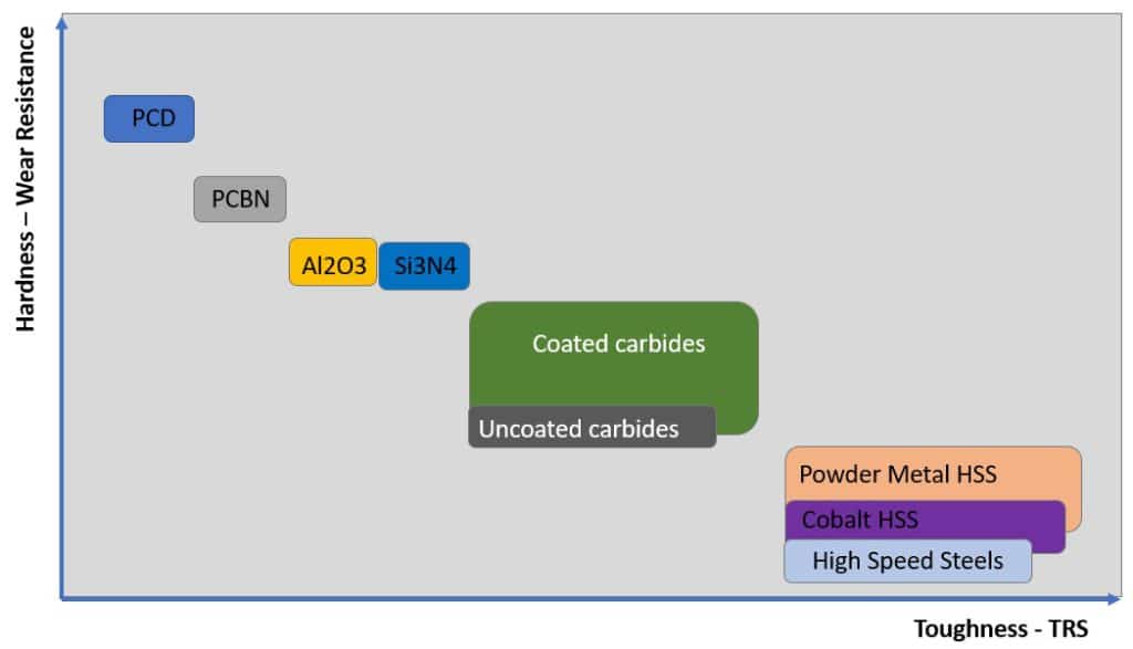
CBN Tools would also be good, but are best for finishing. They are prone to chipping. I've seen good production processes with CBN, where two tools are used, and the finisher gets swapped out to become the roughing tool, once it is worn.
https://us.ns-tool.com/en/products/product_information/cbn/
-
2
-
-
Nothing says "easy to machine" quite like putting a tool to Silicon Carbide.
Try 6 C.
-
1
-
3
-
-
Better late than never! Glad to hear my response was helpful.
-
On 3/25/2024 at 3:02 AM, Giang-TT said:
again with the question: I don't know what is the actual purpose of it - aligning the plane X&Y with machine X&Y , is it just for a better visualization?
I haven't tried it on the real machine but it looks workable on the simulation software, on a table-table AC.The purpose is multi-faceted. You are calculating the output angles, but you are not taking advantage of the architecture of the Post.
The purpose is to give control over the Post and Code Output to the programmer.
One of the things you may not yet know > the Post uses Miscellaneous Integers and Real Numbers > for every Mastercam Operation.
This allows us as Programmers to pass data to the Post, to control the output.
For example, on a Tilt-Trunnion Post, sometimes the calculations make the part "rotate away" from the Operator. The code will work, but you can't easily see and watch.
Wouldn't it be nice if you could use a switch to control the Tilt Axis? Well, you can. The Generic Fanuc 5X Mill Post uses Misc. Integer #10 to control this tilt. (1 or 2 flips between Positive and Negative)
The Post, in the encrypted section, keeps track of things like this.
So, even though you may get G68.2 output that will rotate to the correct orientation on your machine, your XY code may be "skewed" and not match your Tilted Work Plane orientation, because you haven't matched the rotary and linear mapping calculations.
-
Looks like I spoke too soon. Taking this down.
-
1
-
3
-
-
2 hours ago, gcode said:
I'm trying to rough a slot in a Ø50 Ti ring
The slot is 4.25wide 2.25" deep and has a sweep of 170°
I want to use dynamic roughing with a Ø1" carbide endmill
I've got a very nice toolpath going but...
It rapids to about C 160, helixes to depth , roughs all the way back to C0 rapids out and back to C160
then finishes the slot to C170
Is there any way to control where to toolpath starts cutting and in which direction it goes?.
This is a production part and I need it to be as efficient as possible.
Ideally it would start at c10 machine to C0, then rapid back to C10 and finish to C170
Index the geometry (rotate) from the Top. Is the slot essentially "4-Axis" wrapped around a cylinder, or do you need full 5-Axis motion to cut the slot?
-
Look in your Windows Start Menu > scroll down to the "Mastercam" folder, and find the "Quick Reference Card". Lots of shortcuts and handy tips there!
In the "Data Entry Field", instead of typing a letter, Right-Click, and you'll get the full shortcut list.
Also, are you aware you can do "math" in any field with a yellow background? This is a "calculatable value field", and you can not only do simple math, but can use parenthesis as well, to form more complex calculations. For example > (0.8775/2) * 1.414
-
4
-
-
Change-at-Point is the best solution, because those changes are attached to the "chain", so the changes can be made in the Chaining Manager, and the modifications "stick" through regeneration.
-
2
-
-
Note: change "3" to any integer digit 0-9, and you'll get different output. Some useful, others, not so much. But you can run this function multiple times, with different "string" variables to store the output, reuse the same 'result' variable, and just use a different integer value to capture "all ten possibilities".
-
1
-
Wish there was a "collapse all" button in toolpaths manager menu
in Industrial Forum
Posted
Press "E" on the keyboard repeatedly, while your "mouse focus" is in the Toolpaths Manager.
This will toggle between "collapsed" and "expanded", and it will rotate through the different possible states.