


Colin Gilchrist
-
Posts
7,772 -
Joined
-
Last visited
-
Days Won
162
Content Type
Profiles
Forums
Downloads
Store
eMastercam Wiki
Blogs
Gallery
Events
Posts posted by Colin Gilchrist
-
-
I'd suggest the opposite > try adding all three values (XY & Z) on the G43.4 line.
As an alternative, I would suggest having the Post modified to include a G43 Hxx Zxx line, inside the G68.2 call, to pre-position the Tool Tip, to the same position as where the start of the G43.4 toolpath move is.
If you do this, be sure #5006.6 is set to prevent "motion on G49", and also that "G49 comes just before "G69", then you can invoke TCP.
G54 G17 G90
G00 B-90. C-180.
G68.2 X0. Y0. Z0. I90. J90. K0.
G53.1
X-1.8735 Y3. S1000 M03G43 H10 Z6.7
G49
G69
G05 P10000
G43.4 H10
X6.7 Y-1.8735 Z3.
Z-.99445
X6.1
G01 X5.7 F25. -
For Work Offsets in general, my preference is to "assign them to my Plane". (Don't use "automatic numbering" > -1 setting!)
By making some edits to the Post, it is certainly easy to ensure the Work Offset is posted, and having it posted out for before the Tool Change, and also at the Null Tool Change, is certainly easy to do. Sounds like you may have solved some of this already.
If you look in my signature, I've got videos of a Post Processor class I taught up on my YouTube channel. See "MP 101". 28 videos all about Post Processor Development.
-
10 hours ago, evawillms said:
The parameter is correct.
Yes, it was also correct almost 5 years ago, when this thread was started.
-
The other thing to be aware of, is the Entity Attributes Manager. This can be used to "assign" certain geometry and/or geometry properties, to various levels. (Example: force all Solids to "Level 40").
You may already be aware > but you can go into the "Unblank" view, and "unblank" something which has been blanked.
I personally, avoid using Blank/Unblank, however I use Hide/Unhide extensively.
(Say you have a bunch of stuff visible on the screen. You can select "the stuff you want to see and work with", and then press "ALT + E" on the keyboard. It will temporarily "hide" all the other geometry. You can now work with just the stuff you had visible, (measure, or construct new geometry, whatever), and then press "ALT + E" when you are done and wish to bring everything back visible. This is great because you can temporarily hide stuff, then make it visible, without messing with your Level visibility.
-
 1
1
-
-
Did you watch both the MP 101 and MP 301 (5-Axis) Post Class? Technically, there are two courses up. I uploaded part of my 4X Lathe Post Class. I really should go and find the old Lathe videos and upload them as well.
Glad to hear you learned enough to do your own Post edits!
-
-
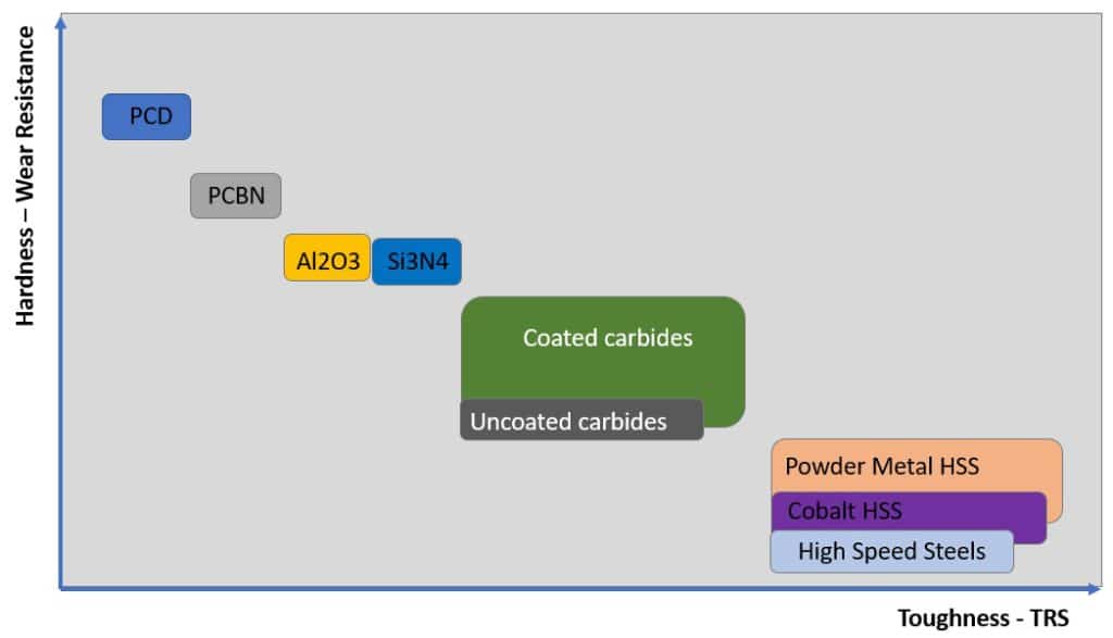
CBN Tools would also be good, but are best for finishing. They are prone to chipping. I've seen good production processes with CBN, where two tools are used, and the finisher gets swapped out to become the roughing tool, once it is worn.
https://us.ns-tool.com/en/products/product_information/cbn/
-
2
-
-
Nothing says "easy to machine" quite like putting a tool to Silicon Carbide.
Try 6 C.
-
 1
1
-
3
-
-
Better late than never! Glad to hear my response was helpful.
-
On 3/25/2024 at 3:02 AM, Giang-TT said:
again with the question: I don't know what is the actual purpose of it - aligning the plane X&Y with machine X&Y , is it just for a better visualization?
I haven't tried it on the real machine but it looks workable on the simulation software, on a table-table AC.The purpose is multi-faceted. You are calculating the output angles, but you are not taking advantage of the architecture of the Post.
The purpose is to give control over the Post and Code Output to the programmer.
One of the things you may not yet know > the Post uses Miscellaneous Integers and Real Numbers > for every Mastercam Operation.
This allows us as Programmers to pass data to the Post, to control the output.
For example, on a Tilt-Trunnion Post, sometimes the calculations make the part "rotate away" from the Operator. The code will work, but you can't easily see and watch.
Wouldn't it be nice if you could use a switch to control the Tilt Axis? Well, you can. The Generic Fanuc 5X Mill Post uses Misc. Integer #10 to control this tilt. (1 or 2 flips between Positive and Negative)
The Post, in the encrypted section, keeps track of things like this.
So, even though you may get G68.2 output that will rotate to the correct orientation on your machine, your XY code may be "skewed" and not match your Tilted Work Plane orientation, because you haven't matched the rotary and linear mapping calculations.
-
Looks like I spoke too soon. Taking this down.
-
1
-
3
-
-
2 hours ago, gcode said:
I'm trying to rough a slot in a Ø50 Ti ring
The slot is 4.25wide 2.25" deep and has a sweep of 170°
I want to use dynamic roughing with a Ø1" carbide endmill
I've got a very nice toolpath going but...
It rapids to about C 160, helixes to depth , roughs all the way back to C0 rapids out and back to C160
then finishes the slot to C170
Is there any way to control where to toolpath starts cutting and in which direction it goes?.
This is a production part and I need it to be as efficient as possible.
Ideally it would start at c10 machine to C0, then rapid back to C10 and finish to C170
Index the geometry (rotate) from the Top. Is the slot essentially "4-Axis" wrapped around a cylinder, or do you need full 5-Axis motion to cut the slot?
-
Look in your Windows Start Menu > scroll down to the "Mastercam" folder, and find the "Quick Reference Card". Lots of shortcuts and handy tips there!
In the "Data Entry Field", instead of typing a letter, Right-Click, and you'll get the full shortcut list.
Also, are you aware you can do "math" in any field with a yellow background? This is a "calculatable value field", and you can not only do simple math, but can use parenthesis as well, to form more complex calculations. For example > (0.8775/2) * 1.414
-
4
-
-
Change-at-Point is the best solution, because those changes are attached to the "chain", so the changes can be made in the Chaining Manager, and the modifications "stick" through regeneration.
-
2
-
-
Note: change "3" to any integer digit 0-9, and you'll get different output. Some useful, others, not so much. But you can run this function multiple times, with different "string" variables to store the output, reuse the same 'result' variable, and just use a different integer value to capture "all ten possibilities".
-
1
-
-
sprogrammer_name = sysinfo(result, 3)
Must initialize 'sprogrammer_name', and you should check to be sure 'result' already exists as a user-defined variable in your Post. (I'd estimate 95% of Posts have a 'result' variable, although the "variable name" may vary.)
-
2
-
-
Remember that every feature in the model which is included (used or not used) is just computational overhead. The more simple your objects are, the faster your calculations. This is especially true for simulation. For simulation, you only care about the "Skin" of the objects that make up the machine. Everything else is a non-value add to the process when collision detection is concerned...
-
1
-
1
-
-
If you have solid pieces which are "adjacent but not intersecting" in some way, they will not boolean join together. The solution is to take one of the pieces, select it, and press "ALT + E" on the keyboard for "hide". Everything else will disappear temporarily. You can then use "Remove Solid History", to take away any history of that one piece, and then use the direct solid modeling functions to "Push-Pull" a face or feature on the solid, so it will get "just a little bigger" and actually intersect the other solid. Once the solid is modified, press "ALT + E" again, and everything will come back. If you did the push/pull right, so the solids properly intersect, you'll be able to complete your Boolean operation.
It also helps in the case of a clamp, if you can "de-feature" the models as much as possible, before importing copies of the solid. I'll use "Modify Solid Feature > Remove" to remove holes and other "internal" features from a model to simplify it, then run Remove History, save the file, and then try to use Boolean Add.
-
1
-
3
-
-
You can use the "Section NCI" C-hook, to break up a Toolpath Operation, and split it into multiple chunks of toolpath code, each with proper approach/retract motion, so you can run the files in sequence on a machine with small memory. After you run "Section NCI" to split a toolpath into multiple files, you must use "Import NCI" to import and stack up the operations. You can then use the NC File naming attributes to append "incrementing numbers" at the end of the file. "File-1", "File-2", "File-3", etc.
Having the "approach/retract" moves inside the NCI Data, is better than asking your Post to add all the necessary approach/retract data, and include the "Tool Change" and "Retract at end-of-file" data.
This solution has existed inside Mastercam since I started using the software with Version 6.1.3, back in 96'-97'.
-
1
-
-
I helped setup a couple of Yasda PX30i machines with 323 Tool Magazines, and the customer quickly learned that they should have bought the 513 tool magazines! I hear Yasda is now building these magazines in a modular way, so you can just keep adding additional blocks of tools if you want to expand beyond 513 tools.
-
1
-
-
49 minutes ago, Giang-TT said:
I don't have much knowledge and experience with the vector functions of the MP language, so I tried to minimize the modifying work as much as possible to make the G68.2 work.
This post is created for a rotary table type machine. In my G68.2 it only has one option formatting - using Euler Angles IJK.
In my post I created a new post block p_twp for calculating the value of X,Y,Z origin and I,J,K angle - based on the data read from NCI (1013 and 1014)
After doing many tests it looks working correctly. But as mentioned before, there is one variable, the "n_tpln_mch" , it appears in some existing post block and makes me confused, it also changes the result of the output code. So if I know what exactly it is, I can still sticking with it, if not, I will try a different way.
Thanks again Colin, I also learned a lot from your post course videos.
The important thing to understand is that some functions were created inside the 5-Axis Post "early in the development" of the Post, and that architecture can be used to support other things. This is the case with 'n_tpln_mch'.
It was originally used to support Nutating Heads/Tables for the G7 function, and using only "mechanical kinematics" to calculate the correct output for a Tool Plane, giving us XYZ P/S (Primary/Secondary) output.
n_tpln_mch gets initialized to '-2'. A setting of '-2' indicates "5-Axis". A setting of "-1" indicates "a path that is not Toolplane Based (3+2 output)". For example Axis Substitution where the input is a Tool Plane, but the math tells the Post to "wrap the rotary axis".
n_tpln_mch gets set to 'top_type' if 'top_map' is active. Otherwise, the post does some other calculations for 'n_tpln_mch', and eventually sets it to 0-4, indicating the type of internal processing (mapping) to achieve the desired output for angles and coordinates.
When 'top_type' is set to '5', then 'n_tpln_mch' also gets set to '5', and then it just overrides all the automatic Nutating internal logic calls, and just calls the "Custom settings, ptop_type_ax and ptop_type_lim" instead.
When G68.2 is implemented using the default architecture For a non-Nutating machine, 'top_map' should be '1', and 'top_type' should be '5', and the only values n_tpln_mch should have are -2 for 5-Axis, and '5' for Plane Mapping (Tilted Work Plane) output.
It is only when 'top_map' is off or 'top_type' is not set to '5', when you'll get the value of 'n_tpln_mch' set in the range between -1 and 4.
In a properly configured Post, using the default architecture, you should only see -2 or 5, or maybe -1 under certain circumstances.
Just for clarity, the only valid values I believe the post should return for n_tpln_mch are: -2, -1, 0, 1, 2, 3, 4, or 5.
-
1
-
-
That document talks about adding only "G68 single axis rotation".
To add G68.2 support, you basically need to set 'top_type' to '5'. This tells MP not to use any of the automatic rotations, and lets you add code to 'pg68' and 'pg68_map', to support the Tilted Work Plane output.
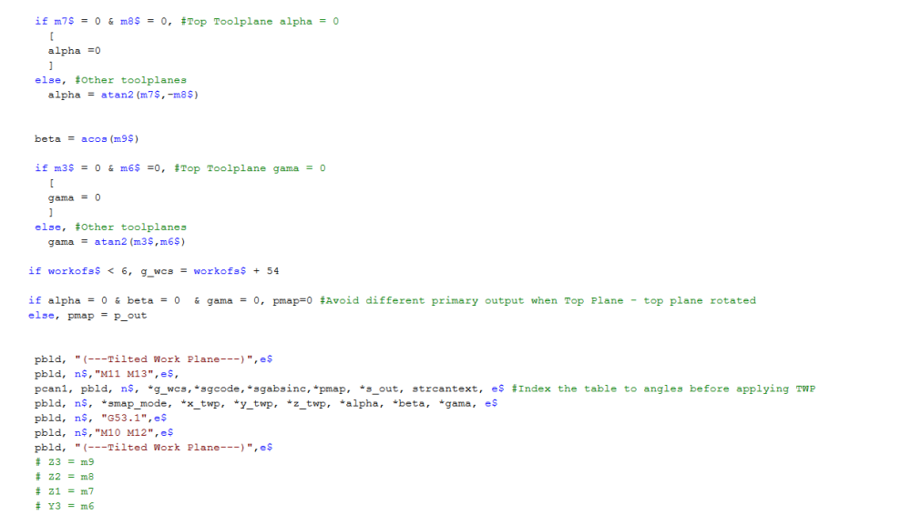
Some sample code (without variable definitions, just look at the structure first, to see if you can figure out what is going on).
# --------------------------------------------------------------------------
# Mapping mode -
# Rotations are always about the zero point
# Only toolplane toolpaths by entire toolpath section use mapping mode
# Modify according to specific post setup
# --------------------------------------------------------------------------
pg69            #Cancel mapping mode
      if top_map,
        [
        #Add your code to cancel mapping mode...
        pbld, n$, smap_mode, e$
        ]

pg68_map        #Map the first postion to the machine
      if p_out | s_out,
        [
        if map_mode = 0,
	  [
	  tmpmtx_xx = mteq(m1$)   #Copy toolplane into temp matrix
	  #####
	  # Find alpha angle
          ieul = -atan2(tmpmtx_zy, tmpmtx_zx)-90
	  #####
	  # Rotate tmpmtx_xx matrix about wcs z by alpha angle - this should make zx equal zero
	  axisx$ = vequ(caxisx)
	  tmpmtx_xx = rotv(ieul , tmpmtx_xx)
	  tmpmtx_yx = rotv(ieul , tmpmtx_yx)
	  tmpmtx_zx = rotv(ieul , tmpmtx_zx)
	  #####
	  #  Find beta Angle between Tool Z Vector and WCS Z about X
	  axisx$ = vequ(aaxisx)
	  jeul = -atan2(-tmpmtx_zy, tmpmtx_zz)  #pay attention to quadrants this is rotated 90 degrees, think of wcs z as an x axis and the vector needs to be measured counter clockwise from there
	  #####
	  # Rotate tmpmtx_xx matrix about wcs x by beta angle
	  axisx$ = vequ(aaxisx)
	  tmpmtx_xx = rotv(jeul , tmpmtx_xx)
	  tmpmtx_yx = rotv(jeul , tmpmtx_yx)
	  tmpmtx_zx = rotv(jeul , tmpmtx_zx)
	  #####
	  #  Find gamma Angle between rotated Tool Plane X Vector and WCS x about z - tmpmtx_zx should be 0,0,1
	  axisx$ = vequ(caxisx)
	  keul = -atan2(tmpmtx_xy, tmpmtx_xx)
	  #####
	  #  Rotate tool plane matrix - xx,yy,zz  should all be equal to 1
	  axisx$ = vequ(caxisx)
	  tmpmtx_xx = rotv(keul , tmpmtx_xx)
	  tmpmtx_yx = rotv(keul , tmpmtx_yx)
	  tmpmtx_zx = rotv(keul , tmpmtx_zx)
	  ]
	if map_mode = 3,
	  [
          #Rotate xabs back
          xabs_s = vequ(xabs)
          rt_tox = vequ(tox$)
          axisx$ = vequ(caxisx)
          xabs_s = rotv(-p_vec_rot, xabs_s)
          rt_tox = rotv(-p_vec_rot, rt_tox)
          temp1_nx = vequ(aaxisx)
          temp1_nx = rotv(-p_vec_rot, temp1_nx)
          axisx$ = vequ(temp1_nx)
          xabs_s = rotv(-s_vec_rot, xabs_s)
          rt_tox = rotv(-s_vec_rot, rt_tox)
          if add_wrk_sht = 0, map_x = vequ(rt_tox)
          else,
            [
            map_x = 0, map_y = 0, map_z = 0 #work shift is turned on, rotate around WCS origin
            ]
          ]
	 ]

pg68            #Enable mapping mode
      map_mode = one
        if p_out | s_out,
          [
            if map_mode = 3,  #G68.2 P3 Q1,2 - two vector method
	      [
              ivec = vequ(m1$)
              pbld, n$, *smap_mode, "P3 Q1", *map_x, *map_y, *map_z, *ivec, *jvec, *kvec, e$
              ivec = vequ(m7$)
              pbld, n$, *smap_mode, "P3 Q2", *ivec, *jvec, *kvec, e$
              pbld, n$, "G53.1", e$
	     ]
	  if map_mode = 0, # #G68.2 - euler angles
	    [
	    pbld, n$, *smap_mode, *map_x, *map_y, *map_z, *ieul, *jeul, *keul, e$
	    ]
          ]

 if p_out | s_out, prv_map_mode = one

##########################
# Original mapping output
#
#      #Primary mapping output
#      ivec = vequ(caxisx)
#     if p_out,
#        [
#        map_r = -p_out
#        pbld, n$, smap_mode, *map_x, *map_y, *map_z, *ivec, *jvec, *kvec, *map_r, e$
#        prv_map_mode = zero
#        ]
#      #Secondary mapping output
#      ivec = vequ(baxisx)
#      if s_out,
#        [
#        map_r = s_out
#        pbld, n$, smap_mode, *map_x, *map_y, *map_z, *ivec, *jvec, *kvec, *map_r, e$
#        ]
#       #if p_out | s_out, prv_map_mode = one
##########################
-
3
-
1
-
-
'top_map' is only the first variable used, to designate that we want to "map toolplane coordinates" to the WCS.
The "mechanism" in the Post was first added to support G7 Rotation for 5-Axis Heidenhain controls.
'top_map' is just a "yes/no" (0 or 1) on/off variable. There is a helper variable called 'top_type' which has 5 possible values: 1-4 select different "automatic rotations" (in the locked portion of the Post), for Heidenhain G7 rotation. You don't want 1-4, you want '5' for Top Type. This lets you use two existing Post Blocks, ptop_type_ax and ptop_type_lim, to be able to calculate your rotation values, and set/check limits.
How to enable G68 in Mastercam generic 5-axis post?
-
Set variable ‘top_map’ to be 1;
-
Modify the rotary axis settings in post block ‘p_nut_restore’ so that they match with the initial rotary settings right above this post block.
-
Modify the value for variable ‘n_saxisx’, ‘n_saxisy’ and ‘n_saxisz’ if necessary. 5X uses ‘n_saxisx’ variables. Toolplane based toolpaths use ‘saxisx’ variables.
-
Modify the value for variable ‘top_type’.
-
If the value of ‘top_type’ is set to be 5, modify the rotary axis settings in post block ‘ptop_type_ax’ and ‘ptop_type_lim’ accordingly. In ‘ptop_type_ax’, also check the axis label, make sure they are set correctly.
-
Modify the mapping logic in post block ‘pg68_map’ and ‘pg68’. Basically the axis to be rotated around may be modified. In ‘pg68_map’, check ‘axisx$’ and make sure it is set to be the right vector to rotate about. In ‘pg68’, check ‘ivec ‘ and make sure it is set to be the right axis vector to rotate about. Also check variable ‘map_r’ is set to be the correct angle. The sign of this angle may need to be changed depending on rotary axis type. For example, ‘map_r’ should be set to ‘p_out’ and ‘s_out’ for head/head machine.
-
The G code for G68/G69 may be modified if necessary.
-
Add code to turn on spindle for G68 mode in ‘p_goto_strt_tl’ and ‘p_goto_strt_ntl’. This is to fix a bug in our 5x post.
-
Add code to turn on G90 mode in ‘p_goto_strt_tl’. This is to fix a bug in our 5x post. The post block ‘p_goto_strt_tl’ and ‘p_goto_strt_ntl’ should looks similar to code below.
p_goto_strt_tl #Make the tool start up at toolchange
……
……
if n_tpln_mch > m_one, #Toolplane mapping mode
[
#Enter your mapping scheme here...
pg68_map
#spindle on
pbld, n$, *speed, *spindle, pgear, e$
pbld, n$, "G43", *tlngno$, *zabs_s, e$
pbld, n$, *sg00, pwcs, *sgabsinc, "X0.", "Y0.", *zabs_s, e$
pcan1, pbld, n$, *sgcode, *xabs_s, *yabs_s, *p_out, *s_out, strcantext, e$
]……
……
p_goto_strt_ntl #Make the tool start up at null toolchange
……
……
##### Custom changes allowed below #####
if n_tpln_mch > m_one, #Toolplane mapping mode
[
#Enter your mapping scheme here...
pg68_map
#spindle on
pbld, n$, speed, spindle, pgear, e$
pbld, n$, pwcs, sgabsinc, *xabs_s, *yabs_s, *zabs_s, *p_out, *s_out, e$
pg68
pbld, n$, *xout, *yout, *zout, e$
]
……
……
-
Add code to update work offset at the end of ‘p_goto_strt_tl’ and ‘p_goto_strt_ntl’.
!workofs$
-
The G68 rotation center will always be WCS origin in our current post. This may need to be fixed if customer wants the rotation center to be the tool plane origin. Be aware of misc integer #6, that would affect the output. The fix needs to be related to the settings of ‘mi6$’.
pg68_map #Map the first postion to the machine
if p_out | s_out,
[
#Rotate xabs back
xabs_s = vequ(xabs)
axisx$ = vequ(caxisx)
xabs_s = rotv(-p_vec_rot, xabs_s)
axisx$ = vequ(baxisx)
axisx$ = rotv(p_vec_rot, axisx$)
xabs_s = rotv(-s_vec_rot, xabs_s)
if add_wrk_sht = 0, map_x = vequ(tox$) #work shift is not turned on, rotate around tool plane origin
else,
[
map_x = 0, map_y = 0, map_z = 0 #work shift is turned on, rotate around WCS origin
]
]
-
Add the highlihghted logic below in post block ‘pg69’ as below.
pg69 #Cancel mapping mode
if top_map & prv_map_mode = one,-
2
-
-
Sure.
Add:
*e$
To force a "blank line" in the NC Code output.
Add that code to the end of 'pheader$', 'psof$', 'ptlchg$', and 'ptlchg0$'.
-
1
-

How to do a undercut program
in Industrial Forum
Posted
Flowline and Surface Finish Contour both support undercutting. Can you share a file?